
Linear motor driven by rotary magnetic fields

A linear motor, rotating magnetic field technology, applied in the direction of magnetic circuit rotating parts, electric components, electrical components, etc., can solve the problems of difficult manufacturing of tooth poles, no application of linear motors, etc., to improve positioning resolution, simple structure, The effect of wide application prospects

Inactive Publication Date: 2009-09-09
黄世章
View PDF2 Cites 11 Cited by
  • Summary
  • Abstract
  • Description
  • Claims
  • Application Information

AI Technical Summary

Problems solved by technology

However, the movement mode of the switched reluctance motor is rotary motion, which has no application in the linear motor
[0006] At the same time, most linear motors are non-stepping motors, which require an independent position feedback system to achieve accurate positioning. Some linear stepping motors are still designed with rotary stepping motors, and the gear poles are difficult to manufacture.

Method used


Image

  • Linear motor driven by rotary magnetic fields
  • Linear motor driven by rotary magnetic fields
  • Linear motor driven by rotary magnetic fields

Examples


Embodiment Construction

[0033] The present invention will be further described below with reference to the preferred embodiments shown in the accompanying drawings.

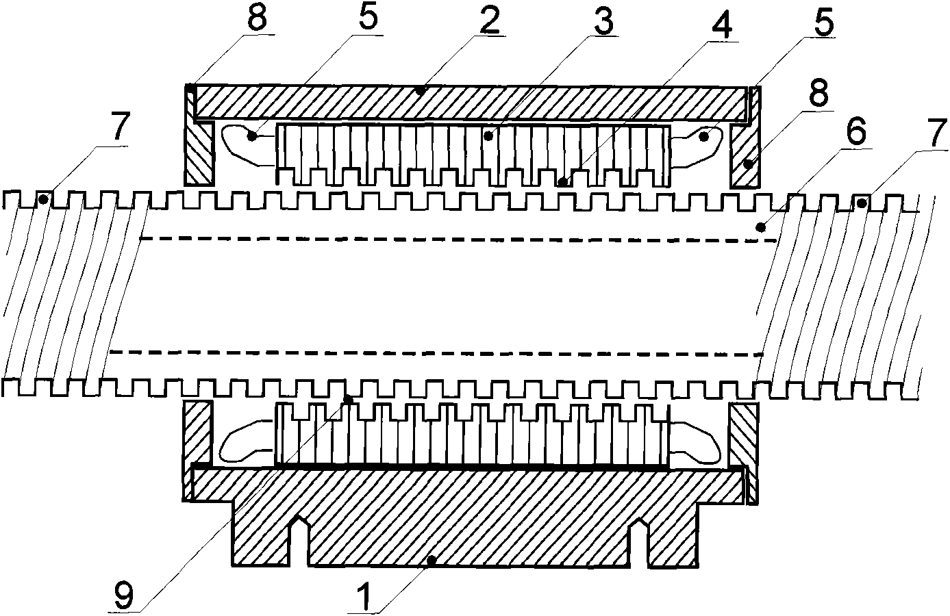
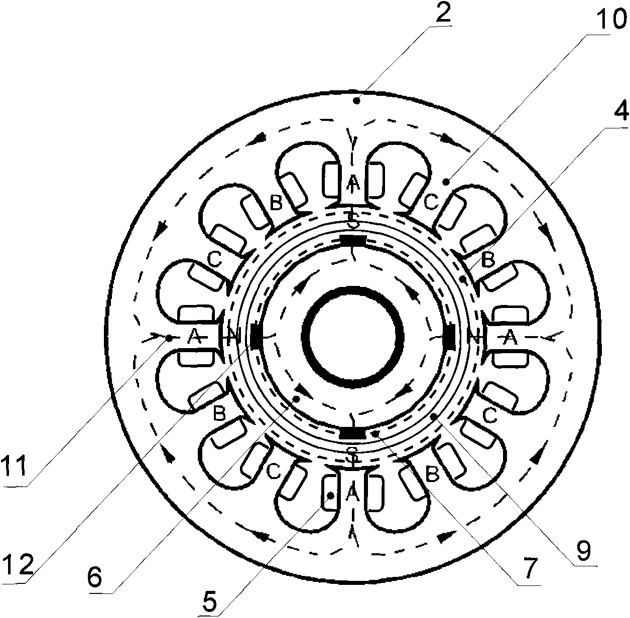
[0034] like figure 1 and figure 2 As shown, a linear motor driven by a rotating magnetic field includes the following parts: a primary frame 1 , a casing 2 , a primary iron core 3 , a primary winding 5 , a secondary mover iron core 6 , and a motor end cover 8 .

[0035] The primary iron core 3 has a casing 2 outside, and is fixed on the primary frame 1 . The end of the primary iron core 3 has a primary iron core pole end thread 4 , and the secondary mover iron core 3 has a secondary mover iron core thread 7 .

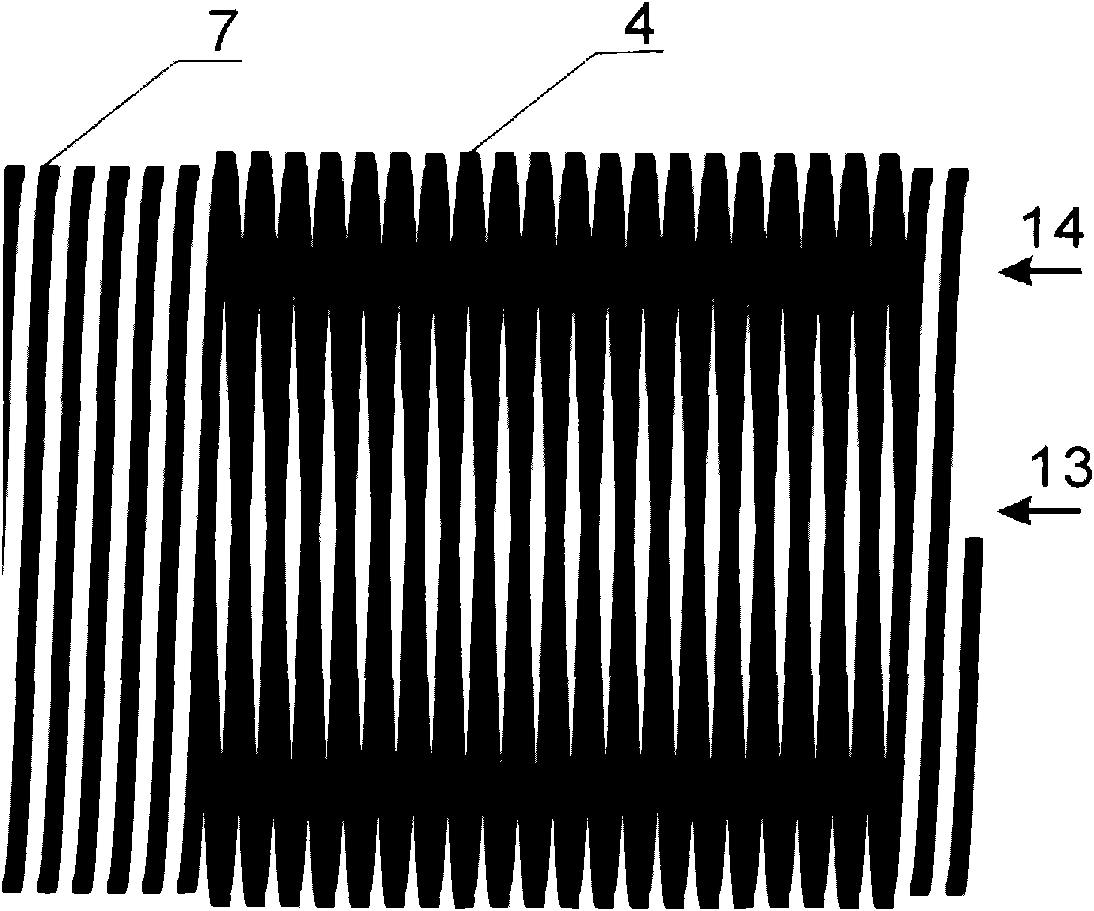
[0036] The primary iron core pole top thread 4 is an internal convex thread, and the secondary mover iron core thread 7 is an external convex thread. The secondary mover iron core thread 7 and the primary iron core pole end thread 4 have the same thread width, the same circumferential pitch of the threads, and are mutually po...


PUM


Abstract

The invention provides a linear motor driven by rotary magnetic fields. The linear motor comprises a primary iron core, a primary winding, a secondary rotor iron core and a guiding device, wherein the primary iron core is encapsulated in a casing; the primary winding is wound on the primary iron core according to the mode of a rotary-magnetic-field motor; the guiding device is used for allowing the secondary rotor iron core and the primary iron core to mutually move only along the axial direction of the secondary rotor iron core; the outer surface of the secondary rotor iron core along the axial direction is provided with a secondary rotor iron-core thread; the inner wall of the primary iron core is provided with a primary iron-core pole-tip thread; and the secondary rotor iron-core thread and the primary iron-core pole-tip thread are mutually positive and reverse. The linear motor has the advantages of needing no permanent magnet materials, reducing the cost for producing and using the linear motor, reducing strong magnetic disturbance to environment and improving thrust-weight ratio. In addition, by adopting a mature integral structure of the rotary-magnetic-field motor, the linear motor has the characteristics of simple structure, low manufacturing cost, radial equilibrium and positioning accuracy, and has broad application prospects.

Description

technical field [0001] The invention relates to a linear motor, in particular to a linear motor driven by a rotating magnetic field. Background technique [0002] Since the linear motor concept was formed in 1840, the linear motor has always followed the design idea of ​​​​the rotary motor, and the magnetic field is all arranged by the traveling wave magnetic field, the winding utilization rate is low, and the thrust-to-weight ratio is small. [0003] Permanent magnets such as neodymium are widely used recently. A permanent magnet reluctance linear motor as disclosed in CN1484364. It consists of a magnetic yoke, a permanent magnet, a secondary mover core, a magnetic isolation plate, a stator core and a winding installed on the stator core. However, the high cost of strong permanent magnets and strong magnetic interference to the environment limit the application of such linear motors. [0004] According to the control mode, the existing linear motors are divided into two ...

Claims


Application Information

Patent Timeline
IPC IPC(8): H02K1/22H02K41/03
Inventor 黄世章
Owner 黄世章
Learn More