Method for measuring burst mode light power and device thereof

A technology of burst mode and measurement method, which is applied in the field of optical communication to achieve the effect of low power consumption, cost reduction and speed reduction

Inactive Publication Date: 2009-09-09
SUPERXON (CHENGDU) TECH LTD
View PDF0 Cites 25 Cited by
  • Summary
  • Abstract
  • Description
  • Claims
  • Application Information

AI Technical Summary

Problems solved by technology

At present, it is difficult to effectively solve the measurement of the burst optical signal power of the optical line terminal (O

Method used


Image

  • Method for measuring burst mode light power and device thereof
  • Method for measuring burst mode light power and device thereof
  • Method for measuring burst mode light power and device thereof

Examples


Embodiment Construction

[0042] The present invention will be further described below in conjunction with the accompanying drawings and embodiments.

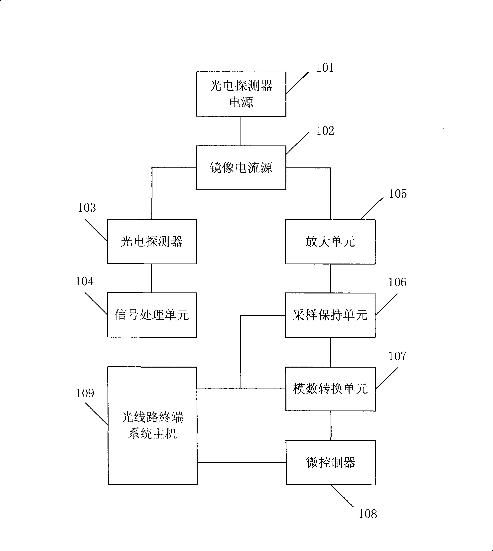
[0043] figure 1 It is a schematic diagram of the structure of an optical line terminal in a specific embodiment of the present invention. Such as figure 1 As shown, the optical line terminal includes a photodetector power supply 101, a mirror current source 102, a photodetector 103, a signal processing unit 104, an amplification unit 105, a sample and hold unit 106, an analog-to-digital conversion unit 107, a microcontroller 108 and an optical line terminal System host 109.

[0044]The photodetector is connected to the signal processing unit and the mirror current source in the optical line terminal respectively, and the mirror current source is also connected to the photodetector power supply and the amplification unit respectively, and the amplification unit, the sampling and holding unit, the analog-to-digital conversion unit and the microcontrolle...


PUM


Abstract

The invention discloses a method for measuring burst mode light power and a device thereof. A photodetector receives an optical signal transmitted by an optical network terminal and generates photocurrent; mirror current source generates mirror current; the mirror current is converted into a voltage signal in an amplification way and transmitted to a sample holding unit; a system hoist controls the sample holding unit at sampling mode; when the voltage signal is stable, the system hoist controls the sample holding unit at hold mode and controls an analog-digital conversion unit to convert the voltage signal into digital quantity; and a microcontroller obtains corresponding light power magnitude after receiving the digital quantity according to mapping relationship, and outputs the light power magnitude to the system hoist by a two-wire serial bus (I<2>C). By adopting the technical scheme, light signal power with hundreds of nanoseconds of length can be measured without expensive high speed device, and lower energy consumption can be realized while reducing cost.

Description

technical field [0001] The invention relates to the technical field of optical communication, in particular to a burst mode optical power measurement method and device. technical background [0002] The passive optical network is a point-to-multipoint system. An optical line terminal (OLT) is connected to multiple optical network terminals (ONT) through a tree-shaped optical fiber link, which not only shares part of the optical fiber link resources, but also distributes the optical line terminal (OLT) cost. At the same time, because the passive optical network does not require midway photoelectric relay or signal processing, it has the advantages of low network construction cost and simple maintenance. [0003] In terms of network technology, in the upstream direction of the passive optical network (PON), the data transmission from each optical network terminal (ONT) to the optical line terminal (OLT) adopts the method of time division multiple access (TDMA), which is also a...

Claims


Application Information

Patent Timeline
IPC IPC(8): H04B10/08H04Q11/00G01J1/42H04B10/075
Inventor 余涛周庭铭邹渊杨杰
Owner SUPERXON (CHENGDU) TECH LTD
Why Eureka
Try Eureka