Hydraulic pump, oil pumping unit, oil pumping module and oil pumping system

A hydraulic pump and oil pumping technology, which is applied in the field of oil pumping modules, oil pumping units and hydraulic pumps, can solve the problems of reducing system reliability and safety, increasing energy consumption costs of oil production systems, increasing system complexity and energy consumption, etc. , to achieve the effect of eliminating potential safety hazards, simple structure, and few parts

Inactive Publication Date: 2009-09-16
杭州坤泽采油设备有限公司
View PDF12 Cites 2 Cited by
  • Summary
  • Abstract
  • Description
  • Claims
  • Application Information

AI Technical Summary

Problems solved by technology

These components not only increase the complexity and energy consumption of the system, but also reduce the reliability and security of the system
[0009] Moreover, at present, major oilfields in my country have entered the high water-

Method used


Image

  • Hydraulic pump, oil pumping unit, oil pumping module and oil pumping system
  • Hydraulic pump, oil pumping unit, oil pumping module and oil pumping system
  • Hydraulic pump, oil pumping unit, oil pumping module and oil pumping system

Examples


Embodiment 1

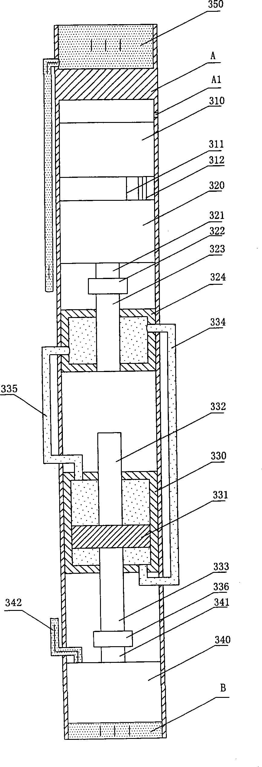
[0045] see figure 1 It is a schematic structural diagram of Embodiment 1 of the oil pumping system of the present invention. The oil pumping system in this embodiment is located in a main pipeline A, and there is underground oil B entering through the oil well at the bottom of the main pipeline A. The oil pumping system mainly includes an oil pumping module, that is, a control mechanism, a hydraulic drive mechanism and an oil pumping unit. The oil pumping unit in this embodiment is composed of a hydraulic pump and an oil well pump, and the control mechanism includes a CPU and a servo motor controller. , encoders and some sensors (such as current sensors, position sensors) and corresponding peripheral circuits, the hydraulic drive mechanism includes a bidirectional pump and an AC servo motor, where the AC servo motor corresponds to the servo motor controller in the control mechanism. The main pipeline A is the fixed support part of the whole system, the components of the whole ...

Embodiment 2

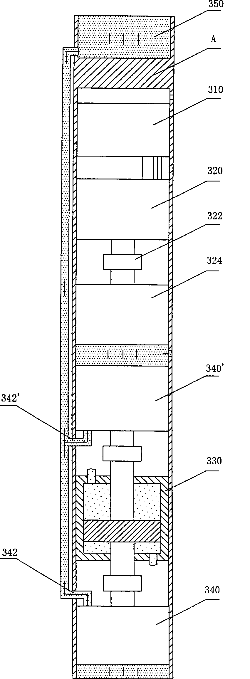
[0050] see image 3 , is a schematic structural diagram of Embodiment 2 of the oil pumping system of the present invention. Different from Embodiment 1, the oil pumping unit in the present invention has two oil pumps, 340' as shown in the figure. In this embodiment, the oil pump outlet pipes 342, 342' of the two oil pumps are combined in Together, they are delivered to the main oil outlet 350 of the oil pumping system.

[0051] Compared with Embodiment 1, this embodiment makes full use of the hydraulic pump 324, and connects the first hydraulic rod 332 with the second oil pump 340', so that when the hydraulic piston 331 of the hydraulic pump 330 reciprocates, the first 2. The second oil pump 340' works in time-sharing, which doubles the oil pumping efficiency.

Embodiment 3

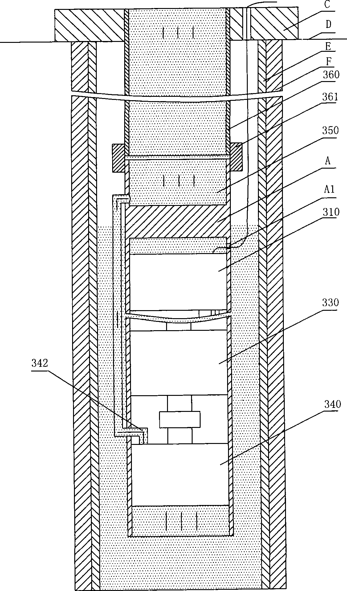
[0053] see Figure 4 — Figure 6 , is a schematic structural diagram of Embodiment 3 of the oil pumping system of the present invention. In the present invention, multiple oil pumping modules can be combined to form an oil pumping system. In an embodiment, the oil pumping system is composed of three oil pumping modules. in, Figure 4 Shown is a schematic structural diagram of the oil pumping module in Embodiment 3 of the oil pumping system of the present invention, the oil pumping module is basically the same as Embodiment 1 or / and Embodiment 2, and will not be repeated here; Figure 5 Shown is the structural diagram of the main oil outlet. The main oil outlet is composed of the main oil outlet 350 and the oil inlets 351 and 352. The oil inlets can be 1, 2, 3, etc., and the figure shows 2 imported oil. Figure 6 It is the connection between the main oil outlet and each oil pumping module, the schematic diagram of the installation, the main oil outlet is connected with the ...


PUM


Abstract

The invention discloses a hydraulic pump, an oil pumping unit, an oil pumping module and an oil pumping system. The hydraulic pump comprises a hydraulic cylinder body, a piston, a first hydraulic rod and a second hydraulic rod, wherein the first hydraulic rod and the second hydraulic rod are connected with the piston; and the second hydraulic rod and the first hydraulic rod extend out of the hydraulic cylinder body along opposite directions. The oil pumping unit comprises a hydraulic pump and a first oil pump which is connected on the first hydraulic rod. The oil pumping module comprises a control mechanism, a hydraulic drive mechanism and the oil pumping unit. The oil pumping system comprises one or a plurality of the oil pumping module(s). The oil outlet of each oil pumping module is connected with the main oil outlet by a pipe. The invention has the advantages of simple transmission, high transmission efficiency, simple structure, fewer parts and components, component-based design,flexible installation and configuration, high reliability and good security.

Description

technical field [0001] The invention relates to an oil extraction machine in an oil field, in particular to an oil pumping system and an oil pumping module, an oil pumping unit and a hydraulic pump used in the oil pumping system. Background technique [0002] Oil production methods in oil fields are divided into self-spray production and artificial lift production. Rod pumping system is the most important artificial lift production method in oil fields at home and abroad. It is mainly composed of three parts: pumping unit, sucker rod and pump. The oil machine is the most important lifting equipment of the rod pumping system. [0003] According to whether there is a beam, the pumping unit can be divided into a beam pumping unit and a beam pumping unit without a beam. For the beam pumping unit, such as the most widely used "kowtow machine", the oil pumping is realized by the motor driving the lever through the rocker link to pull the sucker rod back and forth. Although this s...

Claims


Application Information

Patent Timeline
IPC IPC(8): F04B47/00F04B53/14F04B49/06
CPCF04B5/02F04B47/00E21B43/127F04B9/10F04B9/113F04B47/04F04B49/065F04B2201/0201E21B43/129
Inventor 郝双晖郝明晖
Owner 杭州坤泽采油设备有限公司
Why Eureka
Try Eureka