Charge frequency converter

A frequency converter and charge technology, applied in the fields of instruments, electrical components, scientific instruments, etc., can solve the problems of small charge/current signals, complex processes, and inconvenient measurement of charge/current signals, and achieve stable circuit operation and circuit structure. Simple, easy-to-use effects for multi-channel integration

Active Publication Date: 2009-09-16
INST OF MODERN PHYSICS CHINESE ACADEMY OF SCI
View PDF0 Cites 9 Cited by
  • Summary
  • Abstract
  • Description
  • Claims
  • Application Information

AI Technical Summary

Problems solved by technology

[0003] Under normal circumstances, since the charge / current signal output by the particle detector is generally relatively small, and the charge / current signal is generally inconvenient to measure directly, the usual method is to convert it into a voltage signal and amplify it, and then the voltage signal Performing ADC sampling to indirectly measure the output current of the detector requires a more complicated process and more instruments

Method used


Image

  • Charge frequency converter
  • Charge frequency converter

Examples


Embodiment Construction

[0022] The principles and features of the present invention are described below in conjunction with the accompanying drawings, and the examples given are only used to explain the present invention, and are not intended to limit the scope of the present invention.

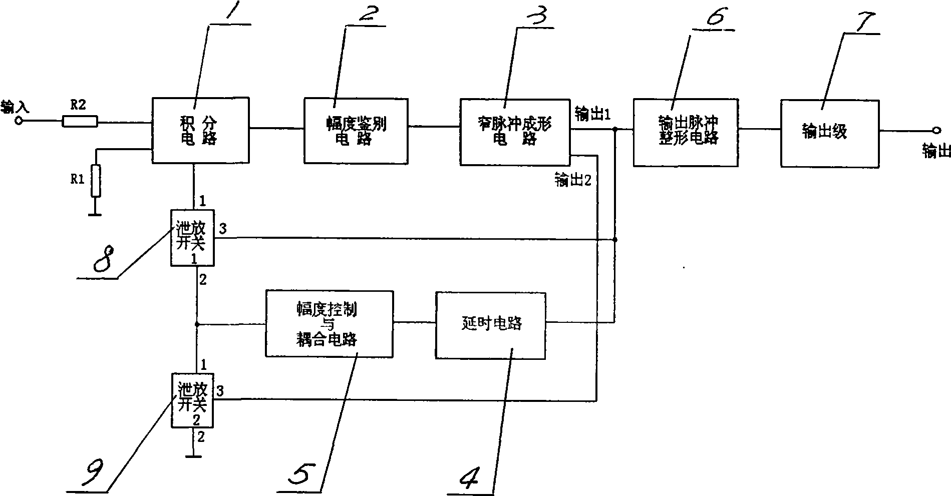
[0023] See figure 1 , a charge-frequency converter, the current signal input terminal P1 is connected to the input terminal of the integrating circuit 1 through the resistor R2; the output terminal of the integrating circuit 1 is connected to the input terminal of the narrow pulse shaping circuit 3 through the amplitude discrimination circuit 2; the narrow pulse The output terminal 1 of the shaping circuit 3 is connected with the input terminal of the delay circuit 4, the input terminal of the output pulse shaping circuit 6 and the control terminal of the first discharge switch 8 respectively; the output terminal of the delay circuit 4 is controlled and coupled by the amplitude The circuit 5 is connected to the disc...


PUM


Abstract

The invention provides a front measurement circuit for measuring charge (current) signal and converting the signal into frequency output. A charge frequency converter is mainly characterized in that a current signal input end P1 is connected with an input end of an integration circuit (1) through a resistance R2; an output end of the integration circuit (1) is connected with an input end of a narrow pulse formation circuit (3) through a range discriminating circuit (2); an input end 1 of the narrow pulse formation circuit (3) is respectively connected with an input end of a time-delay circuit (4), an input end of an output pulse shaping circuit (6) and a control end of a first release switch (8); an output end of the time-delay circuit (4) is connected with a release branch through range control and a coupling circuit (5); an input end 2 of the narrow pulse formation circuit (3) is connected with a control end of a second release switch (9); and an output end of the output pulse shaping circuit (6) is connected with a frequency output stage circuit (7). The invention provides a measurement circuit with simple structure and reliable performance for reading signal of beam intensity detector.

Description

technical field [0001] The invention is a front-end measurement circuit for measuring charge (current) signal and converting it into frequency output. Background technique [0002] In the heavy ion cancer treatment device, the real-time monitoring and measuring circuit of the heavy ion beam current is a key part of the device. The heavy ion beam passes through the beam intensity detector (ionization chamber) and induces a weak current signal. By measuring this weak current, real-time monitoring of the beam intensity / irradiation dose can be realized. [0003] Under normal circumstances, since the charge / current signal output by the particle detector is generally relatively small, and the charge / current signal is generally inconvenient to measure directly, the usual method is to convert it into a voltage signal and amplify it, and then the voltage signal Performing ADC sampling and indirectly realizing the measurement of the output current of the detector requires a more comp...

Claims


Application Information

Patent Timeline
Patent Type & Authority Applications(China)
IPC IPC(8): G01T1/29G01T1/02H03K5/04H03K5/13H03K5/133H03K5/135
Inventor 苏弘李文华董成富马晓莉李小刚千奕
Owner INST OF MODERN PHYSICS CHINESE ACADEMY OF SCI
Why Eureka
Try Eureka