Projection screen and projection method

A technology of screens and horizontal bars, applied in projection devices, optics, instruments, etc., can solve problems such as complex screen assembly

Inactive Publication Date: 2009-09-16
陈和
View PDF1 Cites 10 Cited by
  • Summary
  • Abstract
  • Description
  • Claims
  • Application Information

AI Technical Summary

Problems solved by technology

Focusing reflected light by varying the curvature of the surface of each screen component complicates screen assembly

Method used


Image

  • Projection screen and projection method
  • Projection screen and projection method
  • Projection screen and projection method

Examples


Embodiment Construction

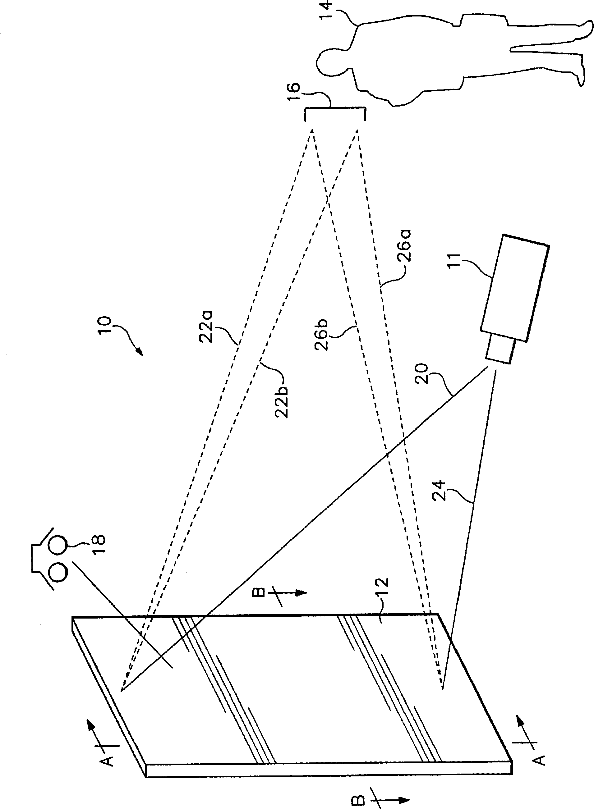
[0022] refer to figure 1 , in the system 10, the front projection light emitted from the projector 11 is reflected by the projection screen 12 to the audience 14 arranged in front of the screen. In a typical exhibition booth or conference room, the audience 14 is often arranged in a wide horizontal area in front of the booth or podium, either sitting or standing. Due to the wide viewing area, a large horizontal viewing angle is required. However, in the vertical plane, in order for the eyes of the viewer 14 to obtain maximum intensity of light, the reflected light should be focused in a very narrow viewing zone 16 (shown in parentheses in the figure). On the other hand, the influence of light emitted by peripheral light sources such as overhead lighting 18 is minimized. Peripheral light projected onto the screen reduces contrast, which can make images appear washed out. On many occasions, the overhead lighting 18 is the main source of ambient light. Of course, other surrou...


PUM


Abstract

A reflection type projection screen consists of a plurality rows of extremely narrow horizontal crossbands so as to cause the images thereof projected on the screen to have wide horizontal view angle in an extremely narrow vertical coverage. Each row of horizontal crossbands is provided with a fore-sight surface which scatters incident light into a wide angle. On each row of horizontal crossbands, incident angles in the vertical direction of the projection screen are different from the bottom to the top of the screen and change hereby so as to reflect light in the vertical direction in an orienting way.

Description

technical field [0001] The invention proposes a brand-new front-projection screen and projection method. Background technique [0002] The invention proposes a projection screen, a projection system and a method. To be precise, it is about a front projection screen and projection method, which can make the projection light scatter in the horizontal direction and reflect in a narrow range in the vertical direction, so that the light of the surrounding environment has the least influence on them. [0003] As we all know, audio and video playback plays an important role in product display and various exhibitions. The audience at the exhibition booth may stand in front of a front-projection screen that is playing images in a circular arc and at a certain distance. Effective image projection requires that the reflected image on the screen has high light intensity and good contrast. . In many exhibition venues, overhead lights shining on the projection screen reduce the contras...

Claims


Application Information

Patent Timeline
IPC IPC(8): G03B21/56
Inventor 陈和
Owner 陈和
Why Eureka
Try Eureka