Traction drive of a rail vehicle for driving and generative braking with load correction

A traction drive, power generation braking technology, applied in electric braking systems, brakes, motor vehicles, etc., can solve problems such as low potential for improvement

Inactive Publication Date: 2009-09-16
KNORR BREMSE SYST FUR SCHIENENFAHRZEUGE GMBH
View PDF1 Cites 8 Cited by
  • Summary
  • Abstract
  • Description
  • Claims
  • Application Information

AI Technical Summary

Problems solved by technology

However, this device has little potential for improvement in terms of weight reduction and torque density, and most of its applications in rail vehicles require a gearbox

Method used


Image

  • Traction drive of a rail vehicle for driving and generative braking with load correction
  • Traction drive of a rail vehicle for driving and generative braking with load correction
  • Traction drive of a rail vehicle for driving and generative braking with load correction

Examples


Embodiment Construction

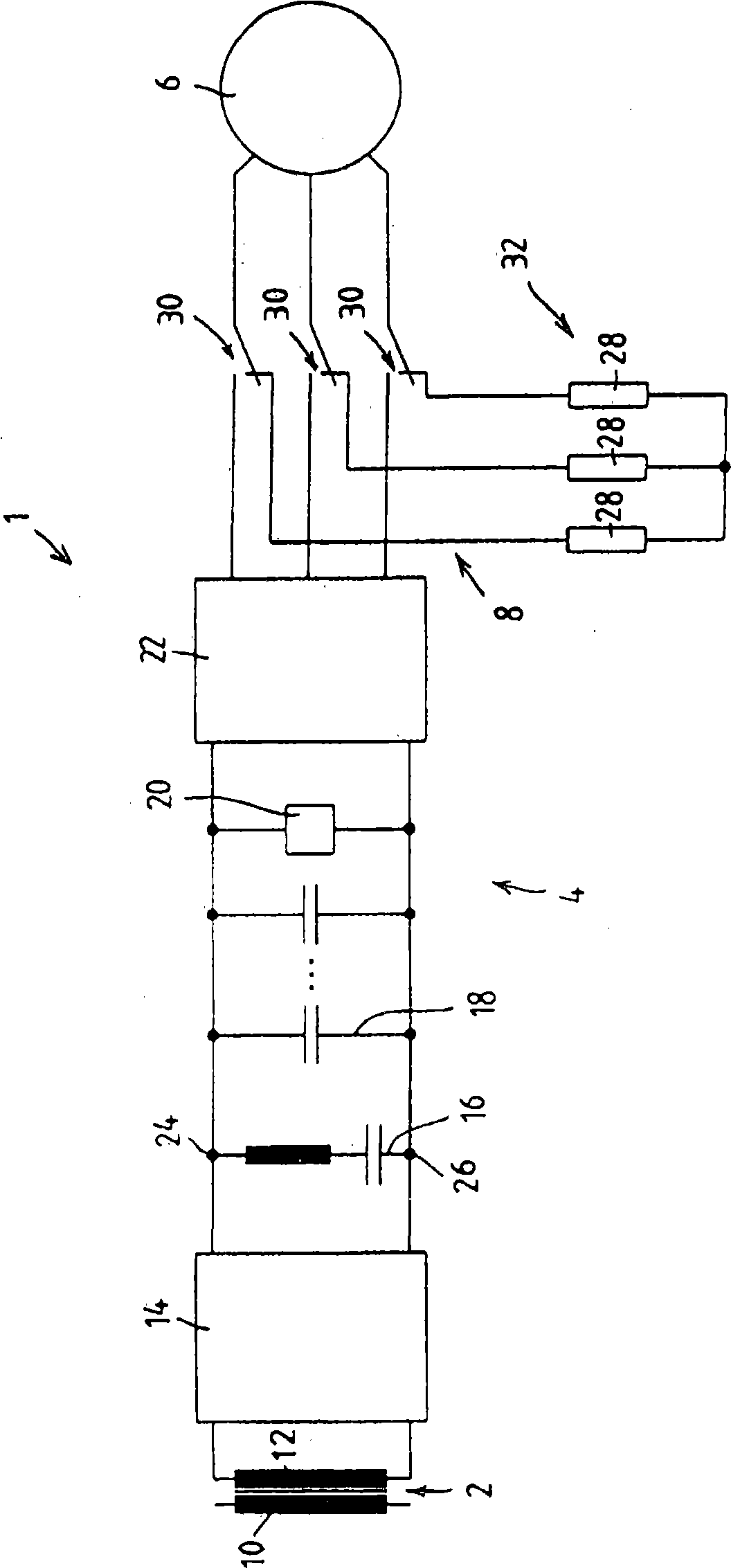
[0043] figure 1The traction drive system 1 for AC trams (also known as AC rail vehicles) is shown in detail in , where 2 represents a traction transformer, 4 represents a traction converter, and 6 represents a permanent magnet excitation synchronous motor , with 8 representing a braking device. The traction transformer 2 has a primary winding 10 and a plurality of secondary windings 12, only one of which is shown here. The traction converter 4 has a four-quadrant regulator 14 , a snubber circuit 16 , a capacitor battery 18 , an overvoltage protection device 20 and a pulse converter 22 on the machine side. The four-quadrant regulator 14 is connected to the secondary winding 12 of the traction transformer 2 on the AC voltage side and in parallel circuit connection on the DC voltage side. The absorber circuit 16 , the capacitor battery 18 , the overvoltage protection device 20 and the DC voltage-side input connection of the motor-side pulse converter 22 are connected in parall...


PUM


Abstract

The invention relates to a traction drive (1) for the driving and generative braking of a rail vehicle or a combination of rail vehicles, at least one permanent-field synchronous motor (6) and a traction current converter (4) being associated with at least one axle of the rail vehicle or combination of rail vehicles. The traction current converter (4) comprises at least one pulse current converter (22) on the engine side, and the clamps of the permanent-field synchronous motor (6) are connected to a change-over switch (30) such that the permanent-field synchronous motor (6) can be connected to a load circuit (32) forming a load, in order to drive the pulse current converter (22) or for generative braking. According to the invention, the load circuit (32) connected to the permanent-field synchronous motor (6) for generative braking is designed and/or controlled in such a way that the characteristic values of the load circuit (32) can be modified according to the loading of the rail vehicle or combination of rail vehicles.

Description

Background technique [0001] The present invention starts from such prior art: [0002] Traction drive systems for drive and regenerative braking (regenerative braking) of rail vehicles or rail trains, in which at least one axle of a rail vehicle or rail train is equipped with at least one permanently excited synchronous motor and a traction converter, and the traction converter has at least one pulse converter on the motor side, the permanent magnet excitation synchronous motor is connected to a changeover switch at its terminals in such a way that the permanent magnet excitation synchronous motor the pulse converter can be switched on for driving, or the load line constituting the load can be switched on for dynamic braking, as described in the preamble of claim 1, and [0003] · Devices for load compensation during dynamic braking of a rail vehicle or rail train comprising an air damper with at least one air spring box, as claimed in the right Requirement 9 described in th...

Claims


Application Information

Patent Timeline
Patent Type & Authority Applications(China)
IPC IPC(8): H02P3/26B60L7/10B60L7/16B60L7/24B60T8/1761
CPCB60L2200/26B60L7/08B60L7/06B60L7/16B60L7/22B60L7/26Y02T10/642B60T8/1705B60L7/24H02P6/24B60L2220/14Y02T10/64
Inventor F·黑勒U·弗里森J·施穆克尔
Owner KNORR BREMSE SYST FUR SCHIENENFAHRZEUGE GMBH
Why Eureka
Try Eureka