Molecular distillation device

A molecular distillation and roller technology, applied in molecular distillation and other directions, can solve the problems of wasting energy, reducing separation efficiency, and reducing the utilization rate of the evaporation surface of the evaporator 2, that is, the inner wall 21, and achieves the effect of saving energy and improving separation efficiency.

Active Publication Date: 2009-09-23
JIANGSU SHAJIABANG CHEM EQUIP
View PDF0 Cites 9 Cited by
  • Summary
  • Abstract
  • Description
  • Claims
  • Application Information

AI Technical Summary

Problems solved by technology

[0005] The deficiencies in the wiper 3 of the above-mentioned molecular distillation device are: the responsibility of the receiving tray 311 of the tumbler 31 that constitutes the wiper 3 is The material is distributed to the inner wall 21 of the evaporator 2. However, since the material introduced from the feed pipe 51 is relatively concentrated, the material, that is, the flow rate of the material liquid is relatively large, and the receiving tray 311 often cannot evenly sprinkle the material to the inner wall 21, so that the material It needs to be scraped for a long time by the wiper roller 316 to form a thin film with uniform thickness in the circumferential direction, that is, a liquid film, on the surface of the inner wall 21, which greatly reduces the utilization rate of the evaporation surface of the evaporator 2, that is, the inner wall 21 , which not only reduces the separation efficiency, but also wastes energy

Method used


Image

  • Molecular distillation device
  • Molecular distillation device
  • Molecular distillation device

Examples


Embodiment Construction

[0016] In order to enable the examiners of the patent office, especially the public, to understand the technical essence and beneficial effects of the present invention more clearly, the applicant will describe in detail below in conjunction with the accompanying drawings in the form of embodiments, but none of the descriptions of the embodiments is a description of the present invention. Restriction of the inventive solution, any equivalent transformation made according to the concept of the present invention which is only in form but not in substance shall be regarded as the scope of the technical solution of the present invention.

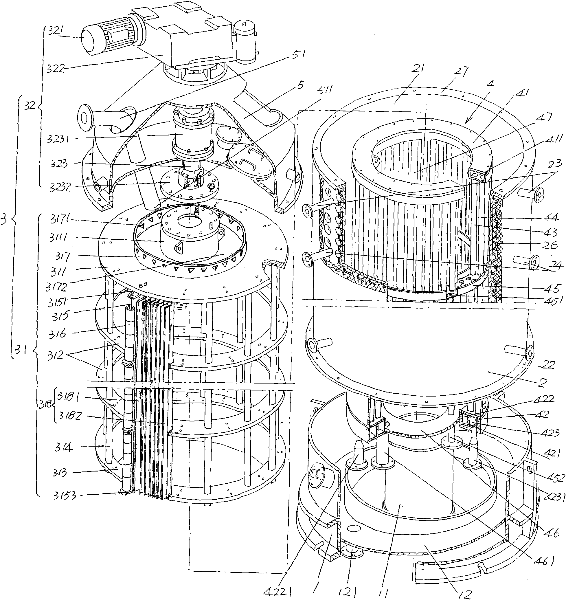
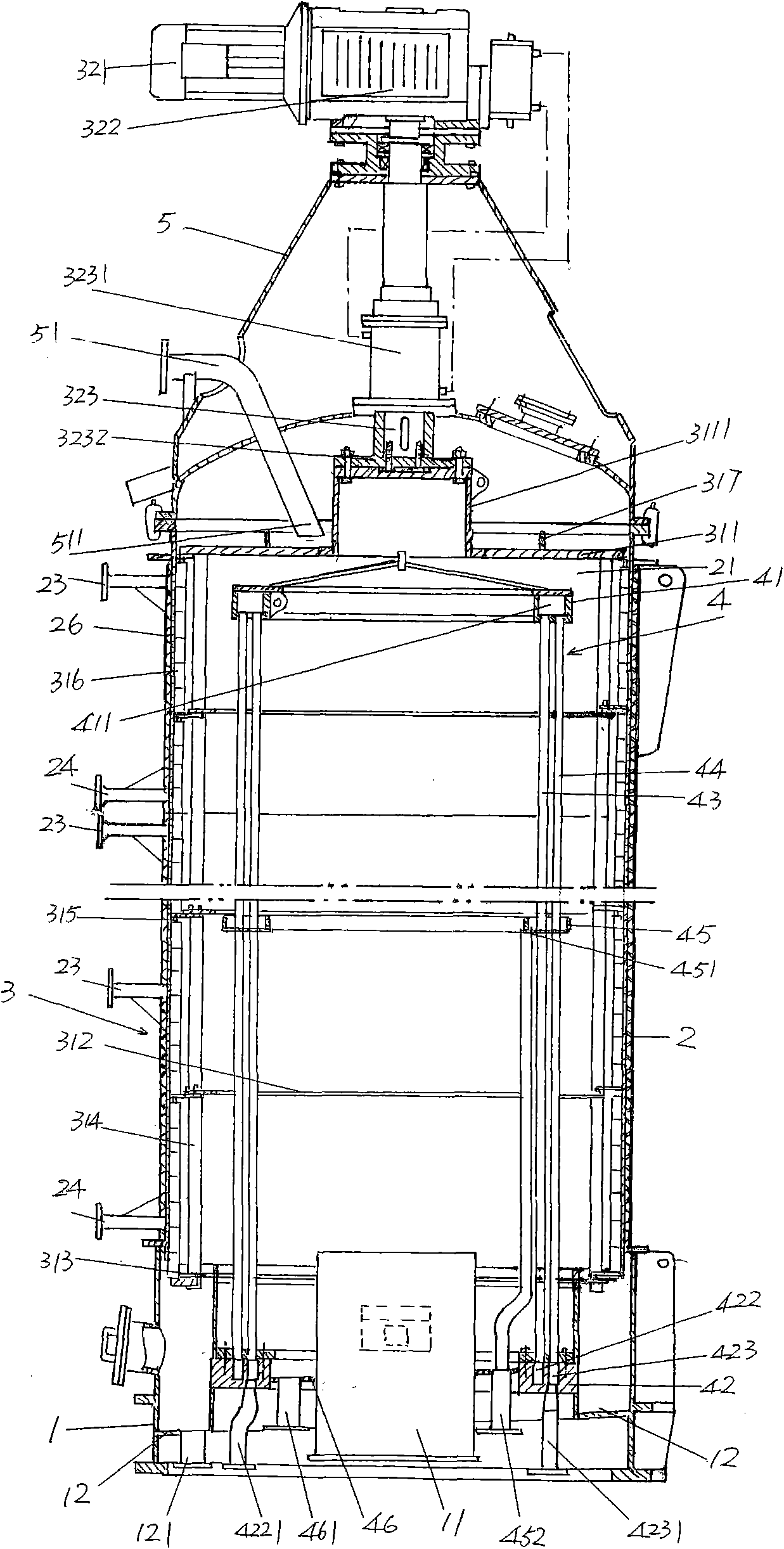
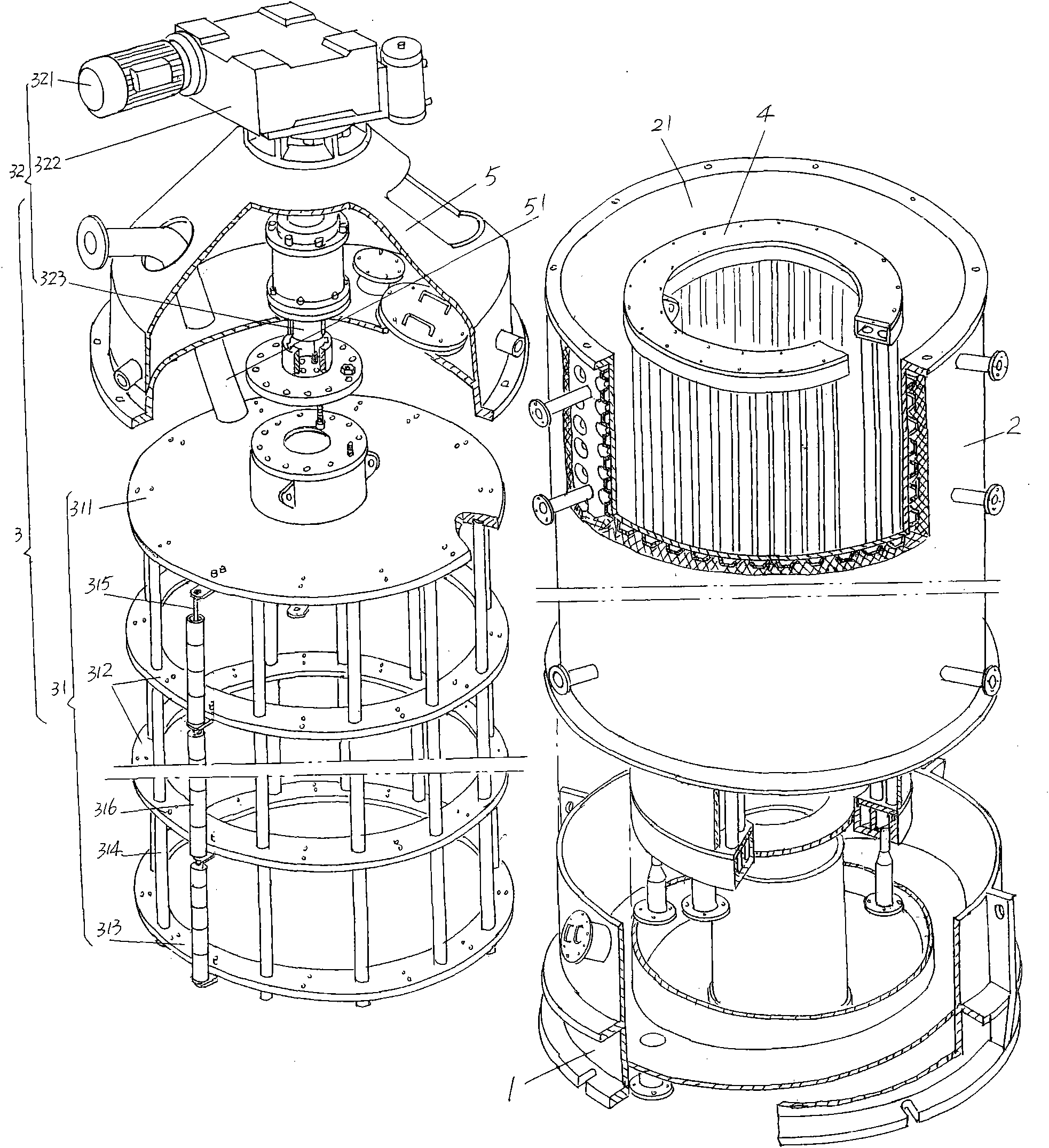
[0017] please see figure 1 and figure 2 , the base 1 is provided, a vacuum tank is arranged in the center of the base 1, and an evaporator 2 is fixed to the upper edge of the base 1 by a fixing flange 22 at the bottom, the evaporator 2 is a honeycomb structure and An insulation layer 26 is provided on the outside, and a heating medium such as...


PUM


Abstract

The invention discloses a molecular distillation device, belonging to the technical field of medicine biochemical engineering equipment. The molecular distillation device comprises a base, an evaporator, a condenser, a cover and a film scraping device, wherein the evaporator and the condenser are arranged on the base, the cover is arranged at the upper part of the evaporator and is provided with a feed pipe, and the film scraping device is connected to the cover and comprises a rotating cage and a rotating cage drive mechanism being in transmission connection with the rotating cage. The rotating cage is arranged in a cavity between the evaporator and the condenser, and comprises a material receiving disc, a set of middle fixed rings, a bottom rotating disc, a set of fixed rods, a set of film scraping roller shafts and a set of film scraping rollers. The set of fixed rods are arranged at intervals, the upper end of each fixed rod is fixed with the material receiving disc, the middle part of each fixed rod is fixed on the set of middle fixed rings in a penetrating way, the lower end of each fixed rod is fixed with the bottom rotating disc, the set of film scraping roller shafts are arranged at intervals to be fixed with the material receiving disc, the middle fixed rings and the bottom rotating disc, and each film scraping roller is sleeved on each film scraping roller shaft. The invention is characterized in that a liquid surrounding weir is arranged on the material receiving disc, and material distributing holes are arranged on the liquid surrounding weir at intervals. The invention improves the separation efficiency, and saves the energy.

Description

technical field [0001] The invention belongs to the technical field of medical biochemical equipment, and in particular relates to a molecular distillation device, which is suitable for the separation of organic mixtures with high boiling point, high viscosity and heat sensitivity and natural products. Background technique [0002] Molecular distillation is usually called short-path distillation. Accordingly, molecular distillation equipment is usually called short-path distillation. The so-called short-path distillation is a special liquid-liquid separation technology carried out under high vacuum (residual gas pressure is less than 10pa). , the evaporated molecules escape the liquid film after being heated and condense rapidly on the built-in condenser after a short distance, which overcomes the constraints of the vapor-liquid balance in the conventional distillation and evaporation, so that the short-path distillation process always maintains a high mass transfer driving ...

Claims


Application Information

Patent Timeline
Patent Type & Authority Applications(China)
IPC IPC(8): B01D3/12
Inventor 王彪吴利东沈军良徐军
Owner JIANGSU SHAJIABANG CHEM EQUIP
Why Eureka
Try Eureka