Gas and oil separating plant for internal combustion engine

A separation device and internal combustion engine technology, applied in mechanical equipment, engine components, machines/engines, etc., can solve the problems of large volume, complex structure of oil-gas separation device, insufficient oil-gas separation, etc., achieve complete oil-gas separation, and facilitate the layout of the whole machine , the effect of simple structure

Inactive Publication Date: 2009-09-23
CHERY AUTOMOBILE CO LTD
View PDF0 Cites 18 Cited by
  • Summary
  • Abstract
  • Description
  • Claims
  • Application Information

AI Technical Summary

Problems solved by technology

[0003] The purpose of the present invention is to provide a separation device that can fully and efficiently separate the oil-gas mixture discharged from the crankcase of an internal combustion engine, so as to solve the problems of the current oil-gas separation device with complex structure, large volume and insufficient oil-gas separation.

Method used


Image

  • Gas and oil separating plant for internal combustion engine
  • Gas and oil separating plant for internal combustion engine
  • Gas and oil separating plant for internal combustion engine

Examples


Embodiment Construction

[0015] The present invention will be further elaborated below according to the drawings and specific embodiments.

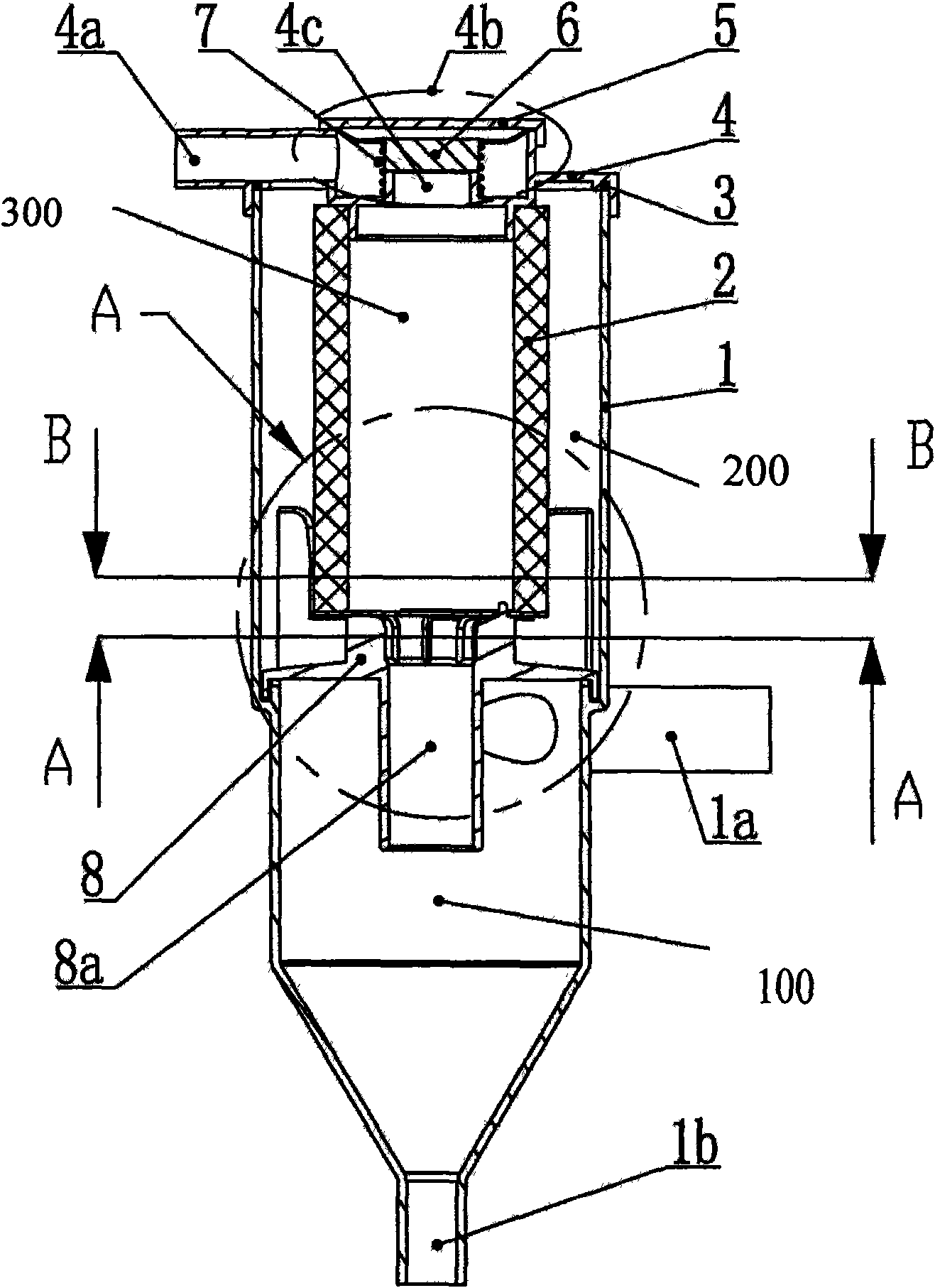
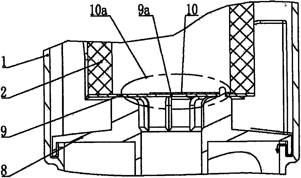
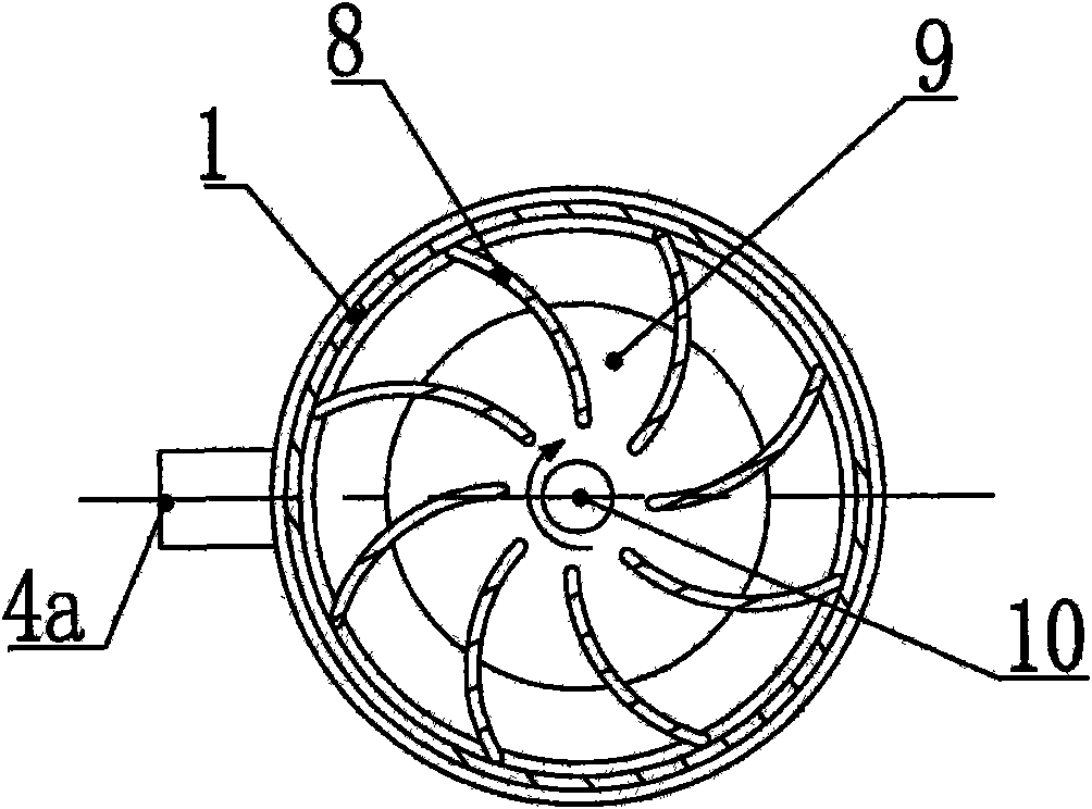
[0016] like figure 1 As shown, the present invention provides a kind of oil-gas separation device of internal combustion engine, and it comprises three parts: the first separation chamber 100 (being cyclone oil-gas separation chamber), the second separation chamber 200 (being baffle plate oil-gas separation chamber) and the 3rd The separation chamber 300 (i.e. the filter screen oil-gas separation chamber), the air inlet 1a of the first separation chamber 100 is directly connected with the crankcase, and the air outlet pipe 8a (i.e. the ascending air pipe) of the first separation chamber 100 passes through the baffle plate 8 to the second The second separation chamber 200, and finally the mixed gas filter is passed to the third separation chamber 300, and enters the intake manifold of the internal combustion engine through the pressure control valve 4b.

[0017] ...


PUM


Abstract

The invention relates to a gas and oil separating plant for an internal combustion engine, which comprises a separating plant shell, an end cover used for sealing the separating plant shell and a filter screen arranged in the separating plant shell; the separating plant shell is provided with an air inlet in the middle part, and the end cover is provided with an air outlet; the separating plant shell and the end cover form a closed cavity which is divided into a first separating chamber arranged at the lower part and a separating chamber arranged at the upper part by a baffle plate which is arranged in the middle of the separating plant shell; the separating chamber arranged at the upper part is divided into two ring-shaped separating chambers by the filter screen, the separating chamber at the outer side is the second separating chamber, and the separating chamber at the inner side is the third separating chamber; the air inlet is tangentially arranged on the side wall of the first separating chamber; the air outlet is arranged on the top of the third separating chamber; a relief valve which can be opened automatically is arranged between the first separating chamber and the third separating chamber; and a pressure control valve which is used for regulating the air pressure in the third separating chamber is arranged at the air outlet which is arranged on the top of the third separating chamber.

Description

technical field [0001] The invention relates to an oil-gas separation device for an internal combustion engine, in particular to a three-stage oil-gas separation device with cyclone separation. Background technique [0002] When the separation effect of the oil-air mixture discharged from the crankcase of the internal combustion engine is not good, the recovery and combustion of the mixed gas will lead to rapid carbon deposition in the internal combustion engine, which will reduce the working performance of the internal combustion engine, accelerate the wear and tear of the internal combustion engine and engine oil consumption, and discharge more harmful gas pollution at the same time surroundings. Ordinary oil-gas separation devices are mostly single-stage, and the separation efficiency is not high. Multi-stage ones are often bulky, complex in structure, and high in cost, so it is difficult to meet the needs of higher emission standards in the future. Contents of the inve...

Claims


Application Information

Patent Timeline
Patent Type & Authority Applications(China)
IPC IPC(8): F01M13/04
Inventor 熊志江
Owner CHERY AUTOMOBILE CO LTD
Why Eureka
Try Eureka