Device for automatically positioning projection lamp wick in lamp cup and method for positioning same

An automatic positioning, lamp cup technology, applied in lighting devices, projection devices, components of lighting devices, etc., can solve the problem of product consistency and stability difficult to guarantee, identification and judgment difficult to maintain consistency, operator safety hazards, etc. problems, to achieve the effect of shortening the lighting time, eliminating potential damage and ensuring quality

Inactive Publication Date: 2009-09-23
江苏森莱浦光电科技有限公司 +1
View PDF0 Cites 8 Cited by
  • Summary
  • Abstract
  • Description
  • Claims
  • Application Information

AI Technical Summary

Problems solved by technology

Most of the current projection lamp power is 200 watts or even higher. Since the lamp must be ignited and stabilized before adjustment, the power consumption is high.
[0013] 2. Affected by human factors: due to the high-intensity light emitted by the projection lamp, the color temperature is about 8500K, which makes the human eyes easily tired, so it is difficult to maintain co

Method used


Image

  • Device for automatically positioning projection lamp wick in lamp cup and method for positioning same
  • Device for automatically positioning projection lamp wick in lamp cup and method for positioning same
  • Device for automatically positioning projection lamp wick in lamp cup and method for positioning same

Examples


Embodiment 1

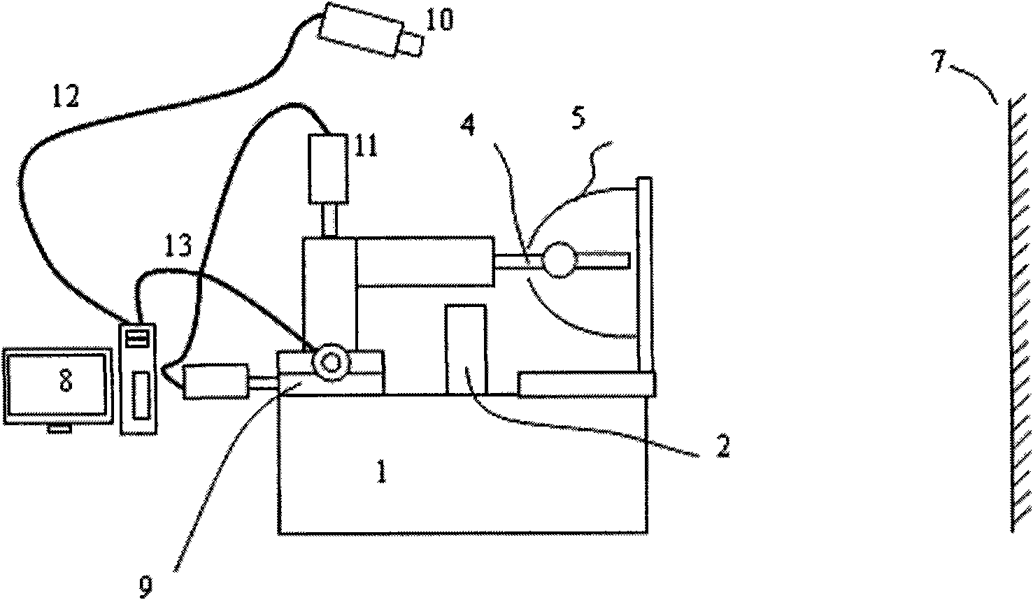
[0056] Vision system: CCD camera, video capture card;

[0057] Image processing system: computer and image processing software;

[0058]Motion control system: a transmission mechanism composed of stepping motor, motion control card, gear or lead screw.

Embodiment 2

[0060] Vision system: USB camera;

[0061] Image processing system: computer and image processing software;

[0062] Motion control system: motion cylinder.

Embodiment 3

[0064] Vision system: camera;

[0065] Image processing system: programmable logic controller (PLC) with image processing function;

[0066] Motion control system: manual translation stage.

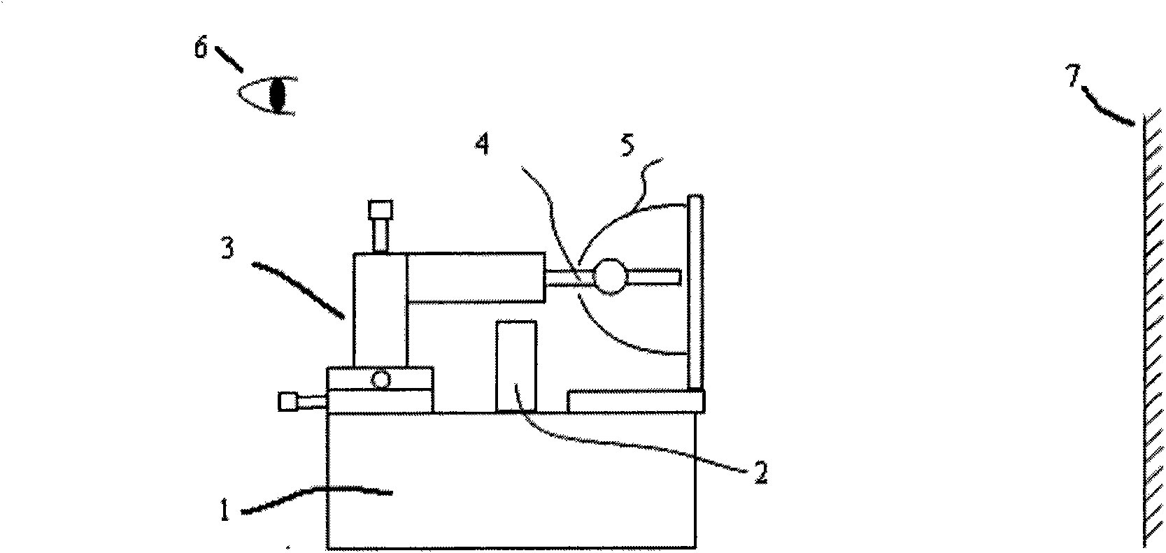
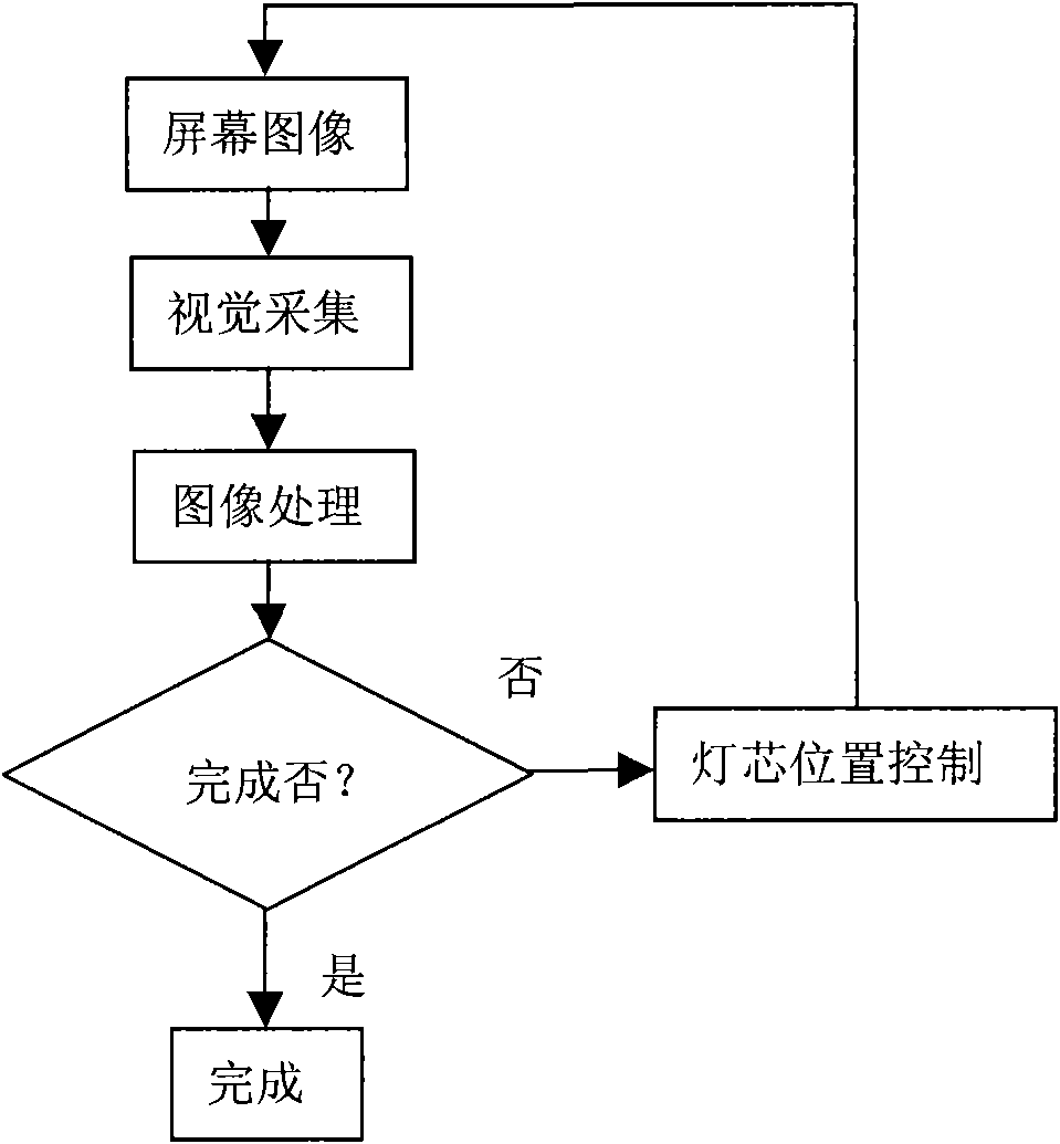
[0067] Correspondingly, the method for automatically positioning the projection wick in the lamp cup in the present invention has the following specific implementation steps:

[0068] The vision system collects and transmits the image projected on the screen 7 by the projection lamp to the image processing system;

[0069] The image processing system first extracts key area parameters such as screen brightness, screen uniformity, contrast, and color temperature after the image data is input;

[0070] Analyze and match the parameters with the empirical data in the database;

[0071] Display performance parameters through the display device;

[0072] Generate motion control parameters and output the parameters;

[0073] Record various data as needed, and display the results of optimization and ...


PUM


Abstract

The invention relates to a device for automatically positioning a projection lamp wick in a lamp cup and a method for positioning the same, which belong to the field of industrial automation control and are applied to achieving safe, effective and highly accordant assembly of the lamp wick and the lamp cup to satisfy requirements on mass production with the lowest cost. The device mainly comprises the following three parts: a vision system, an image processing system and a motion control system, wherein the vision system acquires images projected on a screen (7) by a projection lamp and transmits the images to the image processing system; the image processing system processes the data acquired by the vision system, and compares and analyzes the data with empirical data in a database to get whether the position of the current lamp wick (4) is optimized relative to the lamp cup (5) and generate motion control parameters; and the motion control system adjusts the position of the lamp wick (4) according to the motion control parameters. Through the positioning device and the method, safe operations are achieved, the production quality and the efficiency of products are improved, and energy sources are saved.

Description

Technical field [0001] The invention belongs to the field of industrial automation control, covering the fields of machine vision, computer image processing, automatic control, etc., and particularly relates to a device and method capable of automatically positioning a wick in a lamp cup during a projection lamp assembly process. Background technique [0002] A projection lamp is mainly composed of a lamp cup, a wick (AC and DC ultra-high-pressure mercury lamps, metal halide lamps and other high-brightness projection wicks) and other auxiliary parts. Among them, the position of the wick relative to the lamp cup is the focus of the projection lamp assembly, which directly determines the output, consistency and service life of the projection lamp. [0003] In the existing projection lamp assembly process, human vision and subjective judgment are mainly used to manually find the best position of the wick in the lamp cup. Reference figure 1 , The general assembly steps include: [0...

Claims


Application Information

Patent Timeline
IPC IPC(8): F21V19/02G03B21/20
Inventor 沈立
Owner 江苏森莱浦光电科技有限公司
Why Eureka
Try Eureka