
Multi-purpose ultraviolet ageing system

A multi-purpose, ultraviolet technology, applied in the preparation of test samples, measuring devices, instruments, etc., can solve the problems that the ultraviolet aging system is not targeted, cannot meet the needs of special experiments, and cannot be connected to the instrument, so as to prevent UV light leakage, facilitate heat circulation, protect the environment and human health effects

Inactive Publication Date: 2009-09-23
TONGJI UNIV
View PDF0 Cites 17 Cited by
  • Summary
  • Abstract
  • Description
  • Claims
  • Application Information

AI Technical Summary

Problems solved by technology

It is difficult to obtain a uniform, long-term and stable ultraviolet light source in nature, and the existing ultraviolet aging systems on the market are not targeted, complicated to operate, expensive, and cannot meet the needs of special experiments
For example, the ultraviolet photocatalysis test requires a large space under the light source to place an airtight container, and requires a detection hole on the wall door of the aging box. However, the existing ultraviolet aging system is mostly aimed at performing aging experiments directly under the light source. Usually not large, so there is only a small amount of space available under the system light source, and most of the existing UV aging systems are independent and closed systems, which cannot be connected with external related instruments, so they cannot meet the needs of special experiments

Method used


Image

  • Multi-purpose ultraviolet ageing system
  • Multi-purpose ultraviolet ageing system
  • Multi-purpose ultraviolet ageing system

Examples


Embodiment Construction

[0024] The present invention will be further described below in conjunction with the embodiments shown in the accompanying drawings.

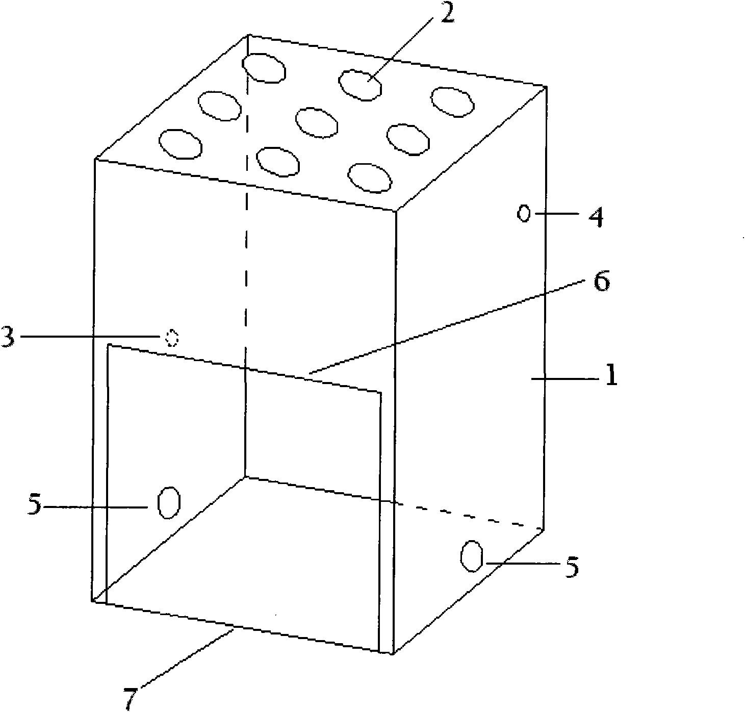
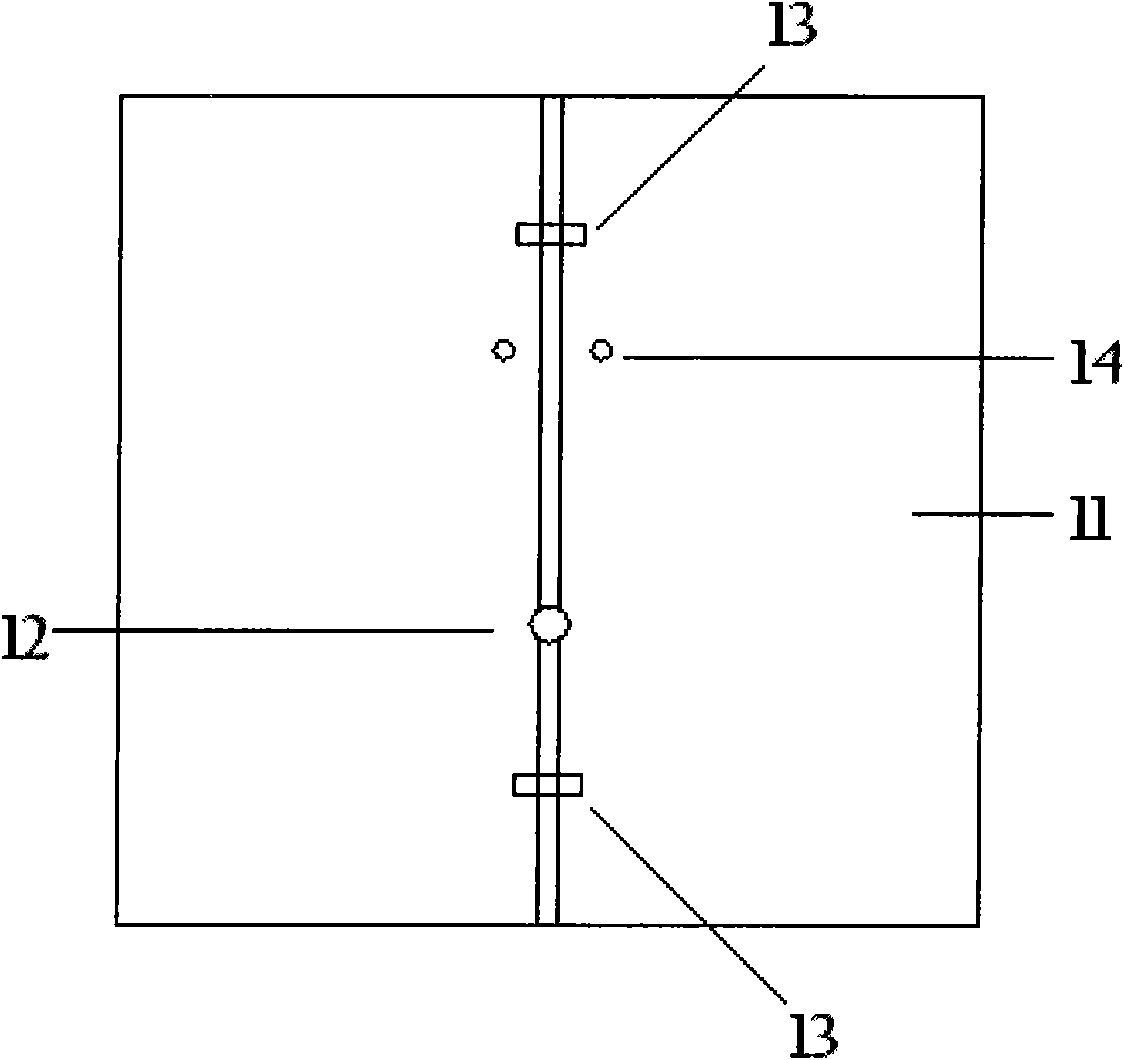
[0025] The system of the present invention mainly includes a main box 1 and a control cabinet 17, the control cabinet 17 and the main box 1 are connected by wires, and the control cabinet 17 provides specific conditions for testing in the main box 1. It may also include a support frame, which may be used in some test situations, such as when the distance between the sample and the light source needs to be adjusted, and the sample can be placed on the support frame.

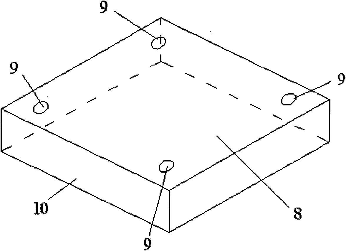
[0026] The main box 1 is made of 1.5mm thick stainless steel material. There is a space inside the box that can accommodate a 400mm cube container or a space of 400mm×400mm×400mm inside the box. Nine GHF125W-03 reflective black lights are installed on the top of the box. High-pressure mercury lamp 2, the right side of the box near the top has an aperture 4 to facilitate the entry a...


PUM


Abstract

The invention relates to a multi-purpose ultraviolet ageing system, comprising a main box body and a control cabinet, wherein the top of the main box body is provided with an ultraviolet lamp and a pinhole used for connecting external equipment, and the control cabinet is connected with the main box body by a conducting wire so as to control the experimental conditions of the main box body. A door body is arranged on the main box body, the bottom of the box door is longer than the bottom of the box body, and both sides of the bottom of the main box body are provided with blast blowers. A top cover which is 10 millimeters away in a horizontal direction is arranged above the top part of the main box body, and the internal space of the box body is at least larger than 400mm*400mm*400mm. The control cabinet comprises a main power adopting a two-way anticreeping switch, a temperature controller adjusting the internal temperature of the box, a time controller controlling the testing time, a light source controlling the ultraviolet lamp and a blower control system controlling the blast blowers, and the backside of the control cabinet is provided with a rectifier for the ultraviolet lamp; and the control cabinet is also provided with a temperature relay and a time relay to control the experiment on the main box body. The invention can automatically and accurately control the experiment, does not leak light, has favorable thermal circulation and can completely satisfy the photocatalysis experiment and various aging experiments.

Description

technical field [0001] The invention relates to an ultraviolet aging system, which can meet various demands on ultraviolet light catalysis and asphalt and asphalt mixture aging tests. Background technique [0002] Ultraviolet light has a huge effect and influence on life and other substances on the earth. It is the main cause of degradation of almost all materials exposed to the outdoors, and it is also a factor that causes the properties of many substances to change or generate activity. It is difficult to obtain a uniform, long-term and stable ultraviolet light source in nature, and the existing ultraviolet aging systems on the market are not targeted, complicated to operate, and expensive, and cannot meet the needs of special experiments. For example, the ultraviolet photocatalysis test requires a large space under the light source to place an airtight container, and requires a detection hole on the wall door of the aging box. However, the existing ultraviolet aging syste...

Claims


Application Information

Patent Timeline
Patent Type & Authority Applications(China)
IPC IPC(8): G01N17/00G01N1/44
Inventor 刘黎萍李剑飞孙立军
Owner TONGJI UNIV
Learn More