Automatic exhaust safety transfusion device

A technology of automatic exhaust and infusion set, applied in the field of medical devices, can solve the problems of human injury, complicated and time-consuming, safety hazards, etc., and achieve the effect of avoiding gravity impact, preventing bubble formation, and ensuring safety.

Inactive Publication Date: 2009-09-30
李林风
View PDF2 Cites 11 Cited by
  • Summary
  • Abstract
  • Description
  • Claims
  • Application Information

AI Technical Summary

Problems solved by technology

If the experience is insufficient and the operation is improper, the liquid and the gas in the dropping funnel will form air bubbles after mixing into the downcomer, resulting in low efficiency of infusion work
Especially when the liquid is emptied due to negligent care and it is too late to replace the new liquid during the infusion process, when the air enters the catheter below the drip funnel, a large section of air bubbles will be formed, and there will be an unexpected phenomenon called blood return, which will cause bubbles in the catheter Serious problems such as the inability to continue infusion due to embolism, blood coagulation into clots and harm to the human body
Removing these bubbles requires complicated and time-consuming operations, and even separates the infusion set and the infusion needle for operation. The treatment methods mentioned in experience articles published in various nursing journals are not scientific, which is not only troublesome, but also likely to cause medical problems sexual infection
[0003] For

Method used


Image

  • Automatic exhaust safety transfusion device
  • Automatic exhaust safety transfusion device
  • Automatic exhaust safety transfusion device

Examples


Embodiment Construction

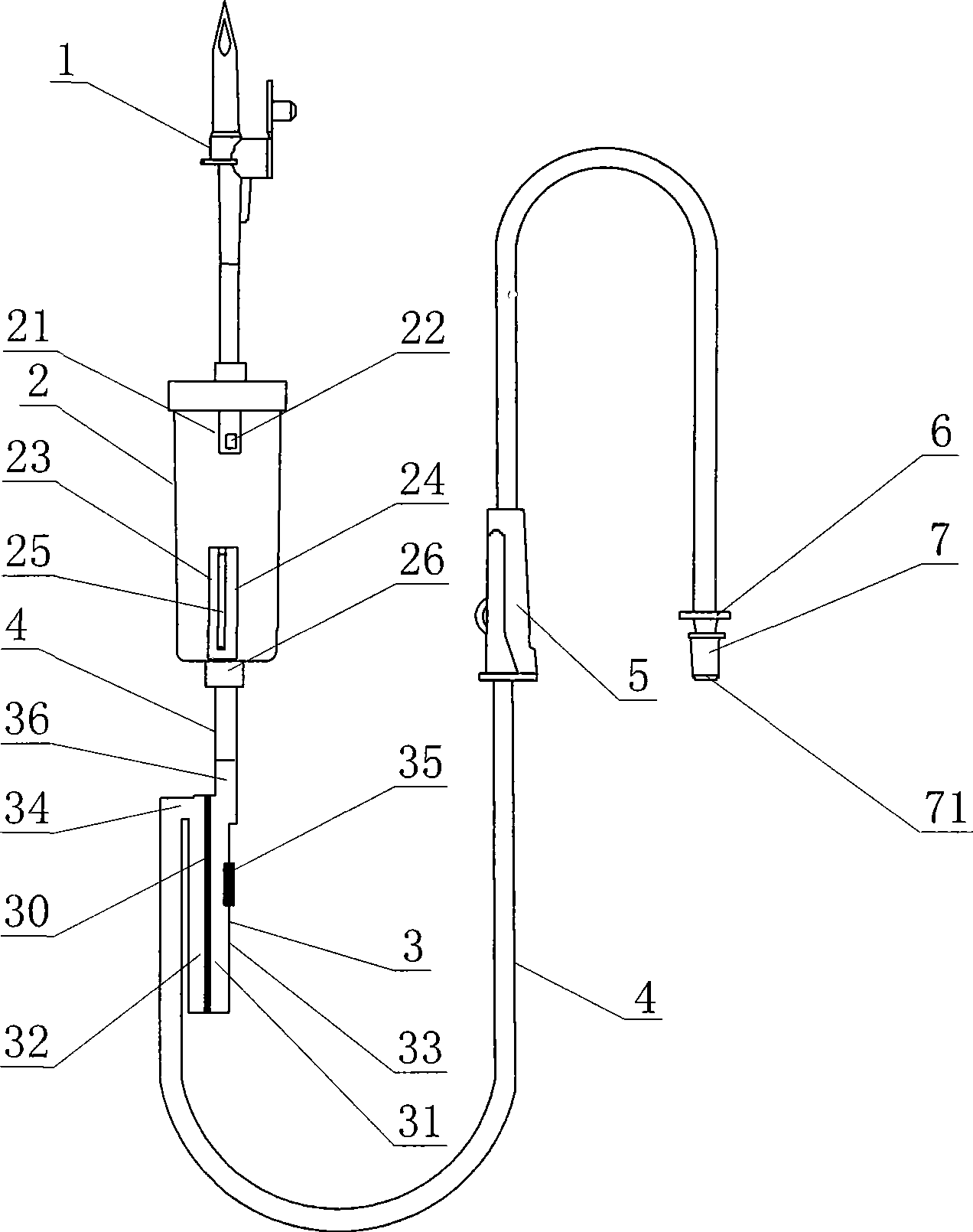
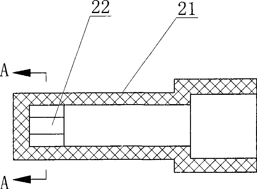
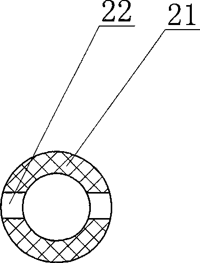
[0018] Such as Figure 1 to Figure 7 As shown, the automatic exhaust safety infusion set of the present invention includes a cork piercer 1, a drip funnel 2 and a conduit 4 communicated with the lower end of the drip funnel 2, a filter 3 installed on the conduit 4 and an adjustment Device 5, in order to make the present invention only need to complete a bottle inserting action to realize automatic air removal in use, without manually operating the exhaust, so as to make its operation more convenient, the lower end of the dripping funnel 2 is installed with a dripping device extending upwards. The lower end of the inner cavity of the bucket 2 is connected to the exhaust pipe 23 of the conduit 4. At least one exhaust infusion hole 25 is provided on the wall 24 of the exhaust pipe 23, and the filter 3 is installed between the dripping funnel 2 and the pipe wall 24. On the conduit 4 between the regulators 5, the filter 3 includes a filter chamber that separates the inner cavity in...


PUM


Abstract

An automatic exhaust safety transfusion device of the invention comprises a bottle stopper puncture device, a dropping funnel, a pipe, a filter and a regulator. The invention is characterized in that the lower end of dropping funnel is installed with an exhaust pipe which upwards extends into the lower end of inner cavity of dropping funnel and is communicated with the pipe. The pipe wall of exhaust pipe is provided with at least one exhaust transfusion opening. Furthermore the filter device is provided on the pipe between the dropping funnel and the regulator. The filter comprises a filtering cavity which divides the inner cavity to a liquid inlet cavity and a liquid outlet cavity through a vertical liquid phase filtering membrane, a liquid inlet and a liquid outlet which are installed at the upper end of filtering cavity and are respectively communicated with the liquid inlet cavity and liquid outlet cavity, wherein the liquid inlet is communicated with the dropping funnel. The liquid outlet is communicated with the pipe positioned below the filter. The side wall of filtering cavity is provided with at least one air exhaust window communicated with the liquid inlet cavity. The automatic exhaust safety transfusion device of the invention effectively settles the problems of easy air bubble forming and difficult air exhaust of prior transfusion device in transfusion process and has the advantages of simple and reliable structure, convenient operation, safe use and suitability for industrial production.

Description

technical field [0001] The invention relates to the technical field of medical devices, in particular to an automatic exhaust safety infusion set. Background technique [0002] The existing infusion set is composed of a cork puncturer, a drip funnel, a catheter, a regulator, a filter and a conical joint, and there are two major problems, one is difficult exhaust, and the other is a potential safety hazard. Excessive gas can only be removed by squeezing the dripping funnel, inverting the dripping funnel or using other cumbersome operation methods when the existing infusion set is used. If the experience is insufficient and the operation is improper, the liquid and the gas in the dropping funnel will form air bubbles after mixing into the downcomer, resulting in low efficiency of infusion work. Especially when the liquid is emptied due to negligent care and it is too late to replace the new liquid during the infusion process, when the air enters the catheter below the drip fu...

Claims


Application Information

Patent Timeline
IPC IPC(8): A61M5/38
Inventor 李林风
Owner 李林风
Why Eureka
Try Eureka