Automatic ladle drainage device

An automatic, ladle technology, applied in the field of ladle drainage device, can solve the problems of affecting the quality of molten steel, disrupting the production rhythm, aggravating the secondary oxidation of molten steel, etc., achieving the effect of shortening the process time, reducing labor intensity and improving the working environment

Active Publication Date: 2009-09-30
石宏帅 +1
View PDF1 Cites 11 Cited by
  • Summary
  • Abstract
  • Description
  • Claims
  • Application Information

AI Technical Summary

Problems solved by technology

Although this utility model can prevent steel slag from clogging the flow steel channel, it cannot achieve the purpose of automatic drainage
Because there must be a certain gap or space between the drainage rod, the nozzle, and the nozzle block, the molten steel flowing into the gap will cause the sintered layer of the drainage sand to thicken and deepen.
Today, with the increasing requirements for the quality of molten steel, automatic ladle drainage is the most basic requirement for drainage sand or drainage devices, because if the ladle cannot be automatically drained, it needs to burn oxygen, which will aggravate the secondary oxidation of molten steel, resulting in inclusions increase, which affects the quality of molten steel, and greatly increases the safety hazards of oxygen-burning operators, and also disrupts the normal production rhythm; on the other hand, the consumption cost of oxygen-burning tubes is much higher than that of drainage rods

Method used


Image

  • Automatic ladle drainage device

Examples


Embodiment Construction

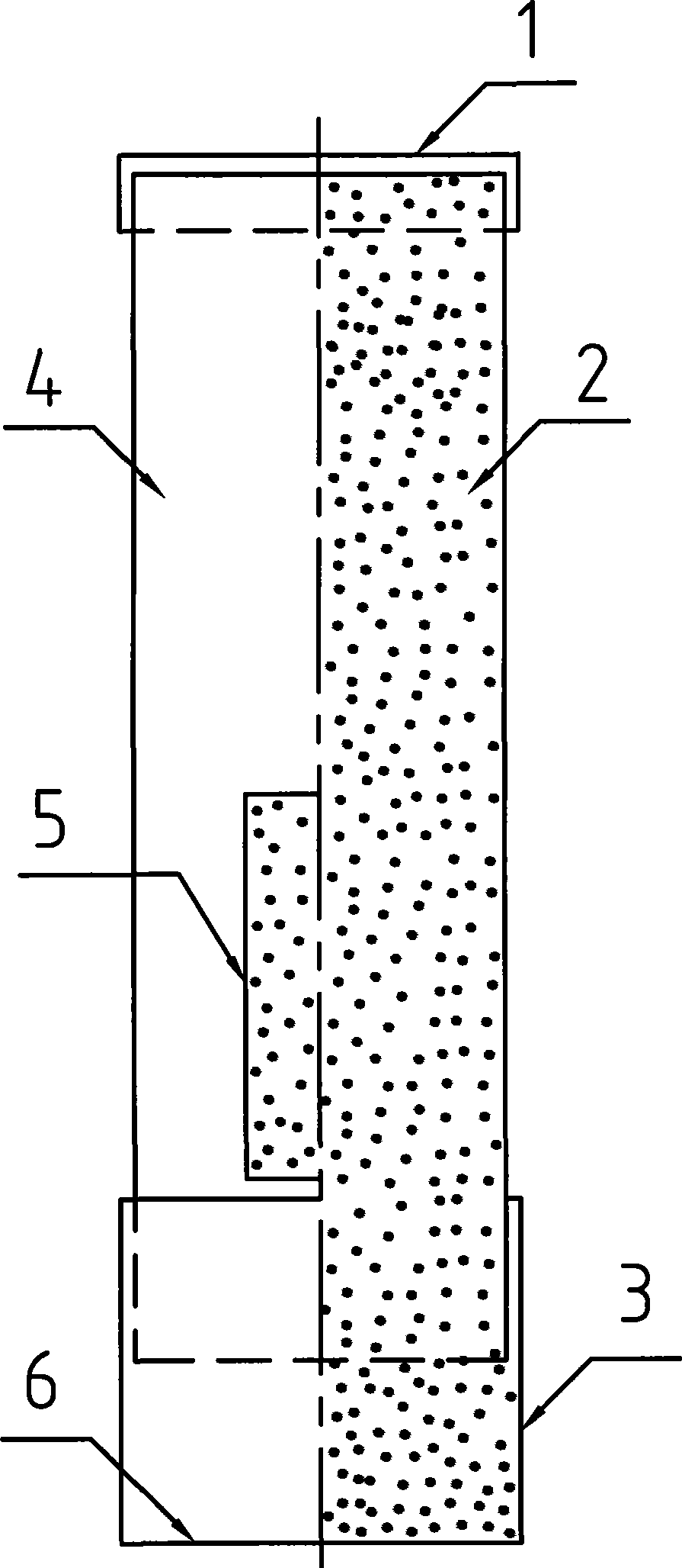
[0017] The present invention will be further described below in conjunction with the drawings.

[0018] In the drawings, the present invention is composed of iron sheet sealing end 1, drainage sand 2, lower steel cylinder 3, upper steel cylinder 4, side holes 5 closed with plastic film and lower opening 6 of the steel cylinder closed with plastic film; The cylinder 4 is inserted into the lower steel cylinder 3 and connected with acrylic adhesive; the side hole 5 has a width of 30mm and a length of 300mm.

[0019] The outer diameter of the lower steel cylinder 3 is 2mm smaller than the inner diameter of the ladle slide plate, which is easy to insert; the outer diameter of the upper steel cylinder 4 is 0.5mm smaller than the inner diameter of the lower steel cylinder 3; the space volume in the device should be close to the ladle upper slide plate, upper nozzle, and nozzle block The volume of the enclosed space is used to calculate the length of the entire device. The purpose is to f...


PUM

PropertyMeasurementUnit
melting pointaaaaaaaaaa
widthaaaaaaaaaa
lengthaaaaaaaaaa

Abstract

The present invention discloses an automatic ladle drainage device applied in a steel making system. The aim of the invention is to greatly reduce the dosage of draining sand, simplify the operating program and simultaneously obtain the purpose of automatic ladle drainage. The technical essential is that a circular barrel with a closed end is composed through inserting one circular cylinder into another circular cylinder with a larger diameter. The side surface of barrel body is provided with one or a plurality of side openings. Draining sand is filled in the barrel body. The side openings are closed by a sheet or a film with temperature of 40 DEG C to 1200 DEG C. In using, the automatic drainage device is inserted along the opening of ladle. Along with the erection of ladle, the draining sand in the barrel automatically fills the space in the filling pipe end and brick cup. The automatic ladle drainage device of the invention is suitable for the using of ladle in all technical conditions of steel making, and has the advantages of simple operation, dust pollution reduction, cost saving, shortened working procedure time, stable automatic drainage rate.

Description

Technical field [0001] The invention relates to a ladle drainage device used in a steelmaking system. Background technique [0002] At present, steelmaking plants at home and abroad generally use the method of putting drainage sand from the top of the ladle into the brick of the ladle nozzle to achieve the function of automatic drainage of the ladle. The disadvantages of this method are serious waste of drainage sand, excessive usage, and a large amount of dust pollution, long process time, and harsh operating environment. [0003] Chinese patent publication number: CN2700029Y; publication date: May 18, 2005, the utility model is named "draining rod for ladle flow steel channel". The application discloses a ladle drainage device, which consists of an upper cover, a tube body, and a drain The material and the lower bottom form a cylindrical rod body; the upper cover and the tube body are made of fusible sheet-shaped plates, the upper cover and the tube body have the same diameter;...

Claims


Application Information

Patent Timeline
Patent Type & Authority Applications(China)
IPC IPC(8): B22D11/103
Inventor 石宏帅杨浩刚
Owner 石宏帅
Why Eureka
Try Eureka