Optical head of computer-controlled plate making machine

A plate-making machine and computer technology, applied in the field of scanning optical heads, can solve the problems of slow scanning speed and inability to achieve high power, and achieve the effect of solving power and channel number problems and being easy to replace independently

Active Publication Date: 2009-09-30
AMSKY TECHNOLOGY CO LTD
View PDF0 Cites 2 Cited by
  • Summary
  • Abstract
  • Description
  • Claims
  • Application Information

AI Technical Summary

Problems solved by technology

The photosetters and photoplotters produced by some companies use this principle to realize simultaneous scanning of 4-8 lasers, but due to the relationship between the transit time of the acousto-optic modulator and the modulation frequency, this method can at most achieve a resolvable 8 channels of light scan at the same time, and cannot achieve high power
Therefore, the scanning speed of the 8-way light is still relatively slow

Method used


Image

  • Optical head of computer-controlled plate making machine
  • Optical head of computer-controlled plate making machine
  • Optical head of computer-controlled plate making machine

Examples


Embodiment Construction

[0019] The invention is an optical head device of a computer-to-plate-making machine, which has a lens, and an optical fiber for scanning is arranged in the lens. The optical fiber is fixed on a silicon chip, and a V-shaped groove array is engraved on the silicon chip. An optical fiber is placed in the V-shaped groove, the diameter of the optical fiber is slightly smaller than the spacing of the V-shaped groove, and a laser diode is independently connected to the tail of each optical fiber. The plane of the V-groove array has a certain angle θ with the scanning direction.

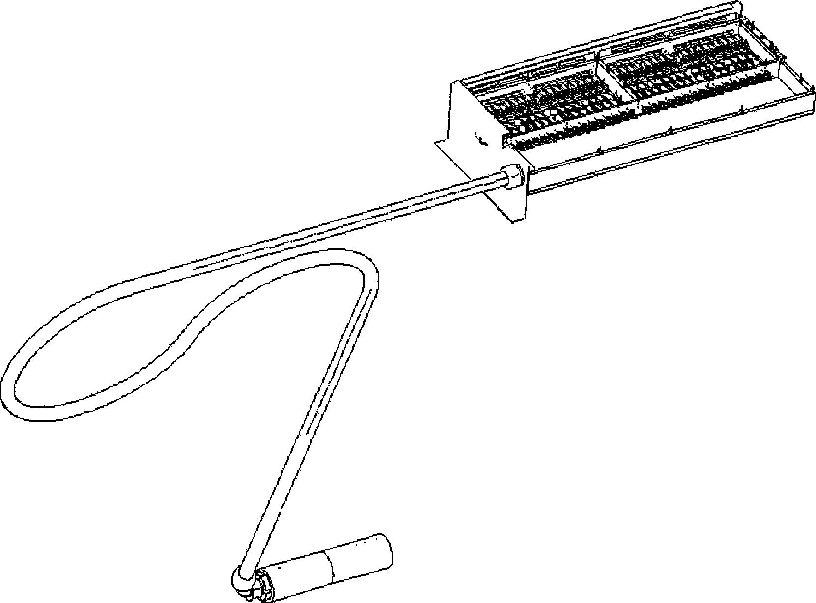
[0020] figure 1 A laser diode with 32 independent pigtailed outputs is shown along with the modulation circuit, optical fiber, V-groove and lens.

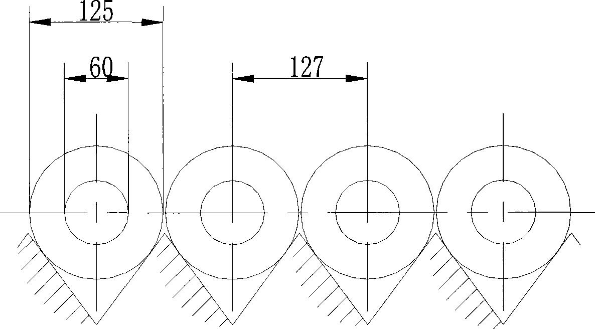
[0021] figure 2 An example of a fiber V-groove array is shown. The V-groove can be obtained by wet etching after exposure of the silicon wafer. The natural V-shaped groove is obtained by using the slow etching speed of the 111 side of silicon. It can also ...


PUM


Abstract

The present invention discloses an optical head of computer-controlled plate making machine, which comprises a lens, with optical fibers arranged in the lens for scanning; wherein, the optical fibers are fixed on a silicon wafer with a V-trough array, an optical fiber is placed in each V-trough, and the diameter of optical fiber is slightly smaller than the pitch of the V-trough; a laser diode is connected separately at the tail end of each optical fiber. In the present invention, the optical fibers in the V-trough array form a plurality of light sources, and each light source is modulated separately according to the image signals, the light sources are combined into one array and scan simultaneously; if the scanning interval of each time is set to be equal to the array width, the result of consecutive scans will form an integral image.

Description

technical field [0001] The utility model relates to the technical field of computer direct plate-making machines, in particular to its scanning optical head. Background technique [0002] Traditional graphic output devices, such as laser imagesetters, generally have three types of laser pixel output methods, capstan type, external drum type and internal drum type. All three technologies are widely used at the same time when the dielectric material is a high-sensitivity material based on silver salt technology. Each has advantages and disadvantages. When the media materials of today's printing industry develop into low-sensitivity materials (such as heat-sensitive plates) that utilize the photodecomposition or photopolymerization effect of polymers, traditional image scanning technology encounters challenges. [0003] The exposure energy of films and photosensitive plates based on silver salt technology is very small, and only needs a laser power of 1mW. Therefore, high-spe...

Claims


Application Information

Patent Timeline
IPC IPC(8): B41B19/00B41B21/08
Inventor 唐晖
Owner AMSKY TECHNOLOGY CO LTD
Why Eureka
Try Eureka