Vehicle brake pedal travel measuring device and measuring method thereof

A technology of brake pedal and pedal stroke, which is applied in the direction of measuring device, the device used to measure the time required to move a certain distance, and the measurement of acceleration, etc., which can solve the reliability problems of the braking system, the loss of foot feel, and the failure safety of the braking system and other problems to achieve the effects of avoiding measurement distortion, intuitive detection results, and high measurement accuracy

Inactive Publication Date: 2009-09-30
CHANGAN UNIV
View PDF0 Cites 20 Cited by
  • Summary
  • Abstract
  • Description
  • Claims
  • Application Information

AI Technical Summary

Problems solved by technology

However, the two methods used at this stage have certain problems.
For the first method, it is not the stroke of the brake pedal that is directly measured, but the force of the driver stepping on the brake pedal. During the conversion process from pedal force to pedal stroke, the conversion relationship of different models is different, so , using this method requires additional pedal rigidity calibration work to obtain the conversion relationship from pedal force to pedal stroke; in addition, because this method installs another plate-shaped sensor on the brake pedal, the driver does not directly Operating the brake pedal, such consequences make the driver unable to correctly perceive the force feedback process of the brake pedal, usually called loss of foot feeling, which affects the normal operation of the driver, thus affecting the authenticity of the experiment
For the second method, its measurement data is accurate and can correctly reflect the stroke of the brake pedal, which is a method widely used at present; however, the main problem of this method is the reliability of the braking system. The braking system is a system that requires strict reliability control. In order to install the sensor in the test, the braking system needs to be disassembled, which will bring potential safety hazards to the braking system and affect the safety of the test.

Method used


Image

  • Vehicle brake pedal travel measuring device and measuring method thereof

Examples


Embodiment Construction

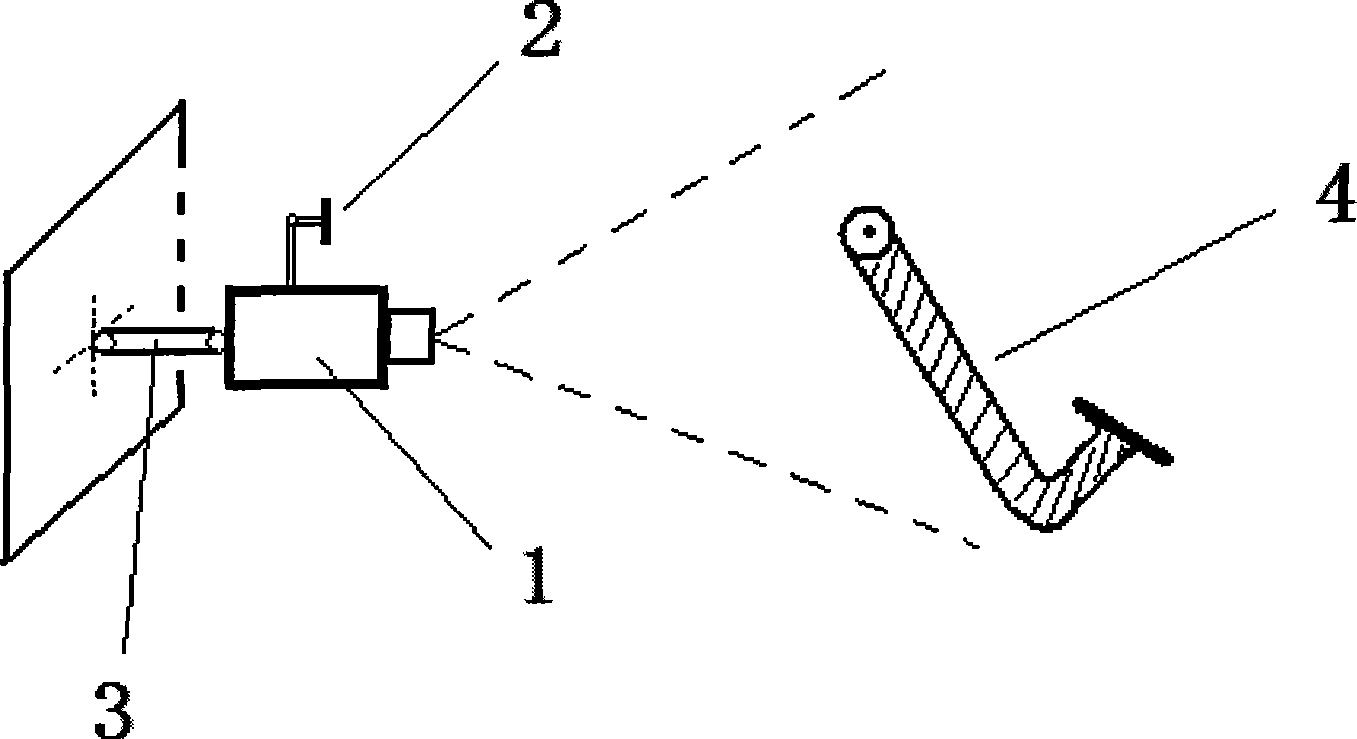
[0027] refer to figure 1 , in the measuring device for the stroke of the vehicle brake pedal, the image acquisition device may be a camera or a camera, and the camera 1 is used in this embodiment. The camera 1 is fixed on the steel plate bracket 3 in the car on the left side of the brake pedal 4 by means of a bracket, and the camera lens faces the brake pedal 4 . The environment where the brake pedal 4 is located is relatively dark, so an LED light 2 is fixed on the camera 1 as a camera light source. The side view shape of the brake pedal 4 is a V shape.

[0028] The camera in this embodiment adopts Zhongxing YJS-01 USB2.0 camera with 6 million effective pixels. The camera is connected to the computer through the USB2.0 data line to receive the moving image of the brake pedal, and obtain the brake pedal at different times through image recognition. The position of the brake pedal can be obtained through geometric transformation to obtain the stroke of the brake pedal, and th...


PUM


Abstract

The invention relates to the technique of brake pedal travel measurement, and discloses a vehicle brake travel measuring device and a measuring method thereof. An image acquisition device is fixed at one side of a brake pedal to acquire the motion images of the brake pedal; a computer is electrically connected with the image acquisition device to receive the motion images of the brake pedal, identifies the different obtained positions of the brake pedal in different time through the images, obtains the travel of the brake pedal through the geometric transformation, and further calculates and obtains the motion speed and acceleration of the brake pedal.

Description

technical field [0001] The invention relates to a brake pedal stroke measurement technology, in particular to a vehicle brake pedal stroke measurement device and a measurement method thereof. technical background [0002] In the field of automobile testing, it is usually necessary to record the driver's use of the brake pedal, such as the frequency of the driver's use of the brake pedal and the severity of the brake pedal. Whether the brake pedal is used or not and the weight of the pedal directly reflects the driver's operating conditions on the vehicle. It is a parameter that needs to be accurately recorded during the car test. This parameter can accurately reflect the driver's driving during the car test. Operating behavior, combined with vehicle and road environment parameters, can reflect the driver’s driving behavior characteristics, and truly reflect the interaction between the driver, vehicle, and road. Therefore, it is usually necessary to use relevant measurements ...

Claims


Application Information

Patent Timeline
Patent Type & Authority Applications(China)
IPC IPC(8): G01B11/03G01P3/68G01P15/00
Inventor 袁伟王畅付锐郭应时张琼
Owner CHANGAN UNIV
Why Eureka
Try Eureka