Manufacturing method of electrode, electric storage device, and intermediate laminate member
A manufacturing method and a technology of an electrical storage device, which are applied in the direction of electrode manufacturing, electrode carrier/collector, electrolytic capacitor, etc., can solve problems such as electrode slurry leakage, and achieve the effects of increasing productivity and increasing delivery speed
- Summary
- Abstract
- Description
- Claims
- Application Information
AI Technical Summary
Problems solved by technology
Method used
Image

Examples
Embodiment approach 1
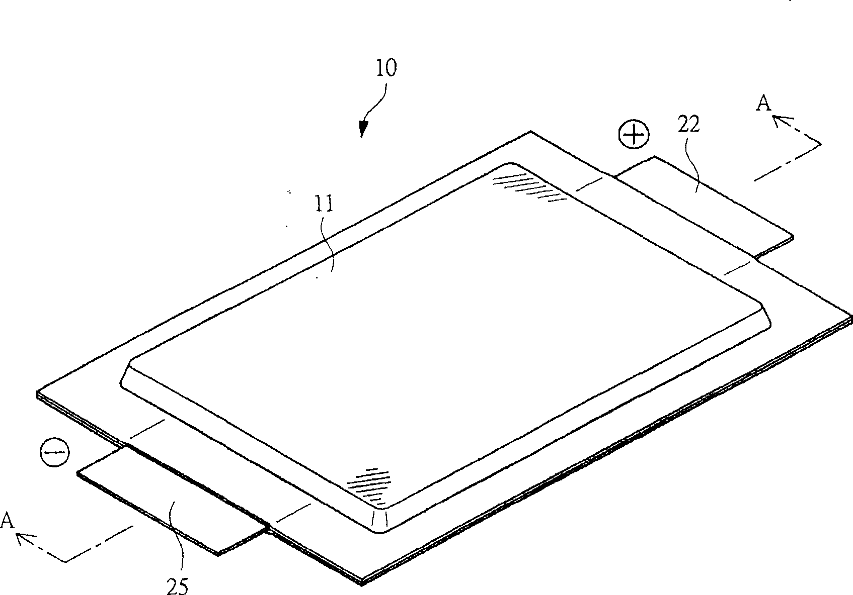
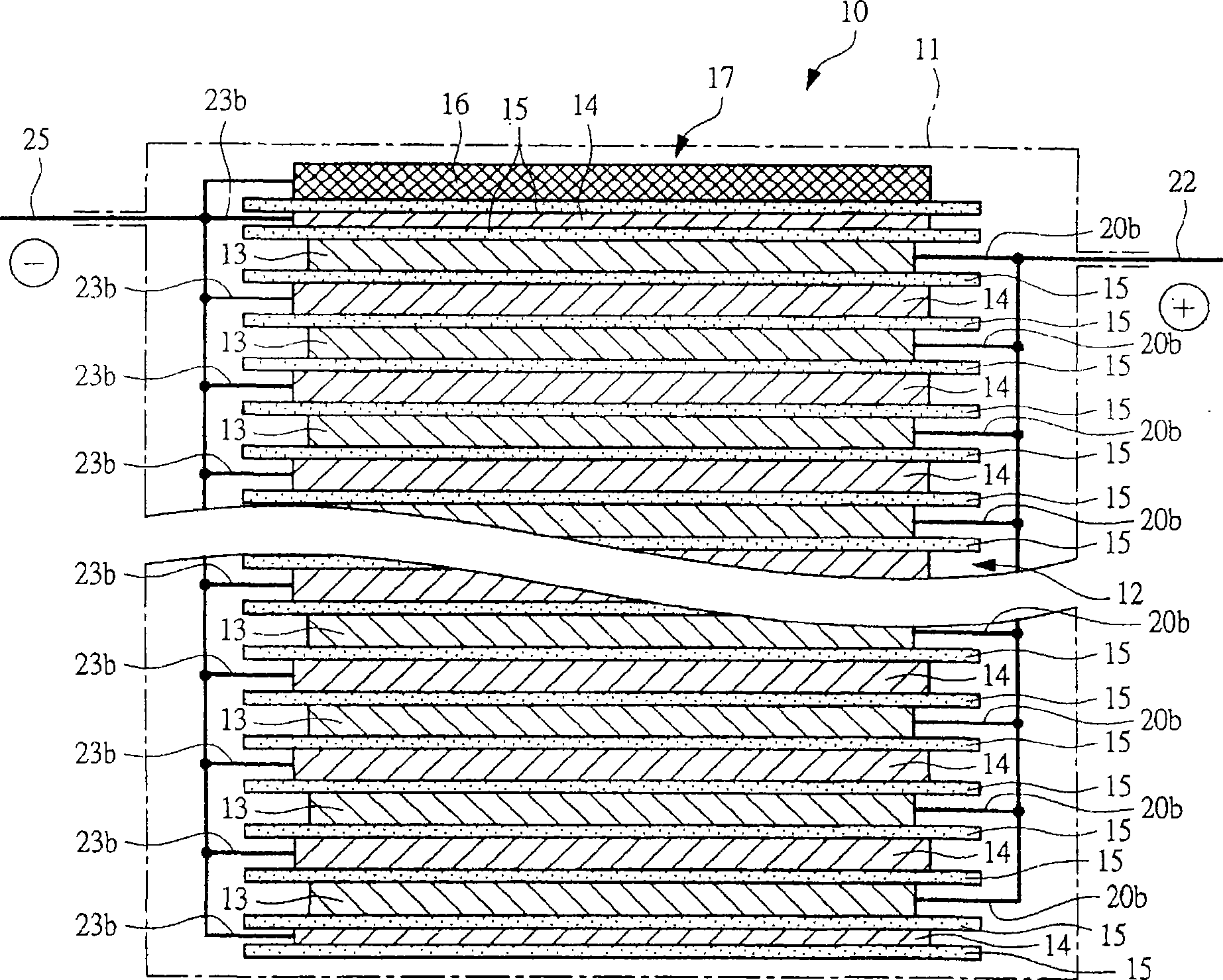
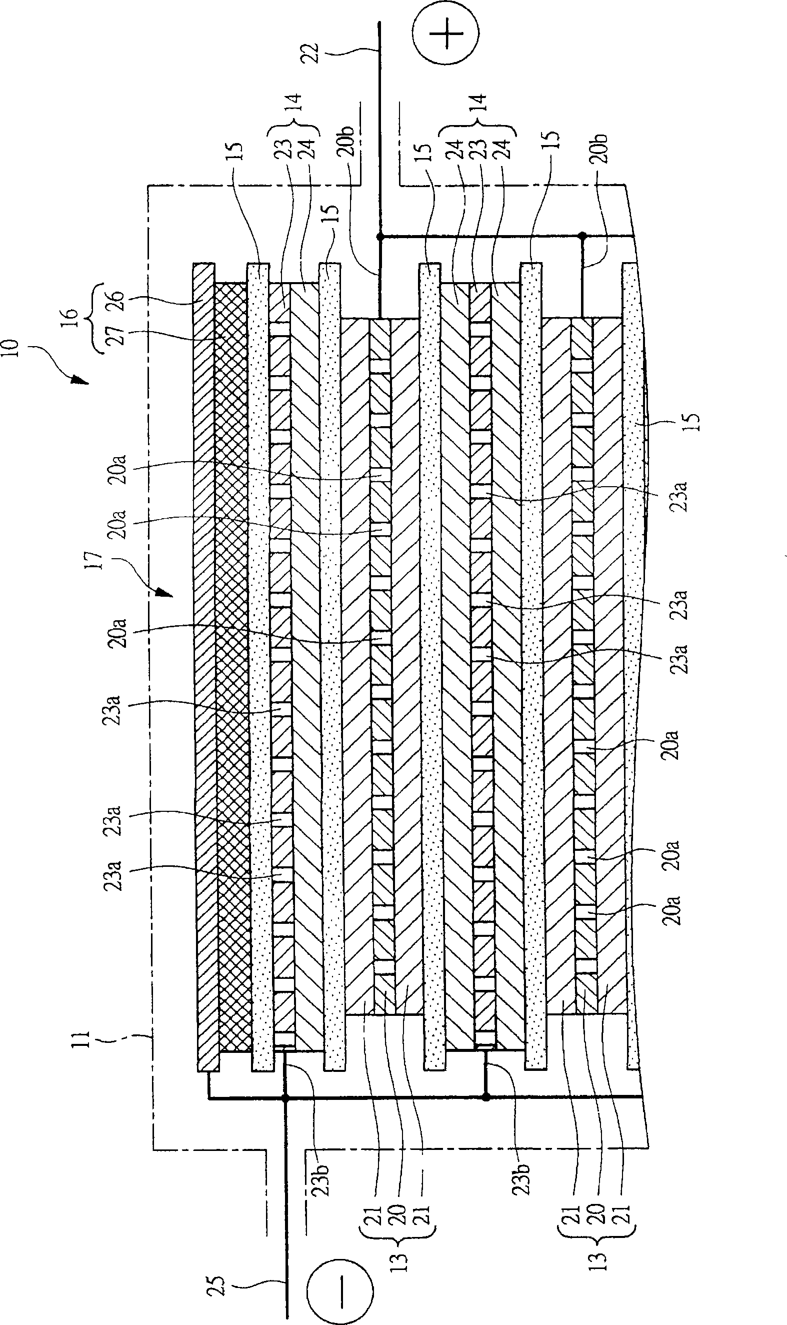
[0063] figure 1 is a perspective view showing the power storage device 10, figure 2 is along figure 1 Line A-A in , schematically shows a cross-sectional view of the internal structure of the power storage device 10 . Such as figure 1 and figure 2 As shown, an electrode lamination unit 12 is accommodated in a laminated film 11 serving as a packaging container. This electrode lamination unit 12 is composed of positive electrodes (electrodes) 13 and negative electrodes (electrodes) 14 that are alternately laminated. A separator 15 is provided between the positive electrode 13 and the negative electrode 14 . In addition, a lithium electrode 16 is arranged to face the negative electrode 14 at the outermost portion of the electrode stack unit 12 . A separator 15 is provided between the negative electrode 14 and the lithium electrode 16 . The three-electrode lamination unit 17 is composed of the above-mentioned electrode lamination unit 12 and the lithium electrode 16 . In...
Embodiment approach 2
[0120] The description of Embodiment 1 relates to a current collector lamination unit in which a plurality of current collector materials are laminated.
[0121] As described in Embodiment 1, one embodiment of this current collector lamination unit is a structure in which current collector materials are stacked via, for example, a thin film material (blocking layer). The current collector lamination unit having the above configuration can increase the transport speed compared to the case where the porous current collector material is transported without inserting the thin film material. For example, horizontal shipments can be made faster. That is, by laminating the current collector material on both surfaces of the film material with a certain degree of adhesive force, the strength of the film material is enhanced when the laminated current collector material having holes is transported.
[0122] In the above-mentioned structure in which the current collector material with o...
Embodiment approach 3
[0163] In the current collector lamination unit described in Embodiments 1 and 2, holes penetrating through the current collector material are formed in the plurality of current collector materials laminated with the barrier layer interposed therebetween. In this through hole, as described in the first embodiment, the electrode paste is applied and then dried to form an electrode composite layer. In forming this electrode composite layer, the electrode composite layer is filled in the via hole depending on the case. In addition, in the first embodiment Image 6 , 10 , 11 exemplifies the structure in which the electrode paste is not filled in the through hole, but it can also be, for example, as Figure 25 , 26 , 27 shown in the filling. Since there is a thin film material as a barrier layer, it is notified that the electrode composite layer formed by drying the electrode paste filled in this way does not come off but remains in the through hole. However, after the electro...
PUM
| Property | Measurement | Unit |
|---|---|---|
| Specific surface area | aaaaa | aaaaa |
Abstract
Description
Claims
Application Information
 - R&D
- Intellectual Property
- Life Sciences
- Materials
- Tech Scout
- Unparalleled Data Quality
- Higher Quality Content
- 60% Fewer Hallucinations
Browse by: Latest US Patents, China's latest patents, Technical Efficacy Thesaurus, Application Domain, Technology Topic, Popular Technical Reports.
© 2025 PatSnap. All rights reserved.Legal|Privacy policy|Modern Slavery Act Transparency Statement|Sitemap|About US| Contact US: help@patsnap.com