High-gain low-profile null feed array antenna

A high-gain, antenna technology, applied in antennas, slot antennas, electrical components, etc., can solve the problems of inconvenient installation and portability of three-dimensional three-dimensional structures, and achieve the effect of reducing antenna efficiency, improving antenna efficiency, and reducing antenna side lobes

Inactive Publication Date: 2009-09-30
SOUTHEAST UNIV
View PDF0 Cites 17 Cited by
  • Summary
  • Abstract
  • Description
  • Claims
  • Application Information

AI Technical Summary

Problems solved by technology

Although the reflector antenna omits the complex feed network, the feed placed at the focal point in front of the reflector makes the overall profile height of the antenna several times the working wavelength
Therefore, its three-dimensional structure is not easy to install and carry

Method used


Image

  • High-gain low-profile null feed array antenna
  • High-gain low-profile null feed array antenna
  • High-gain low-profile null feed array antenna

Examples


Embodiment

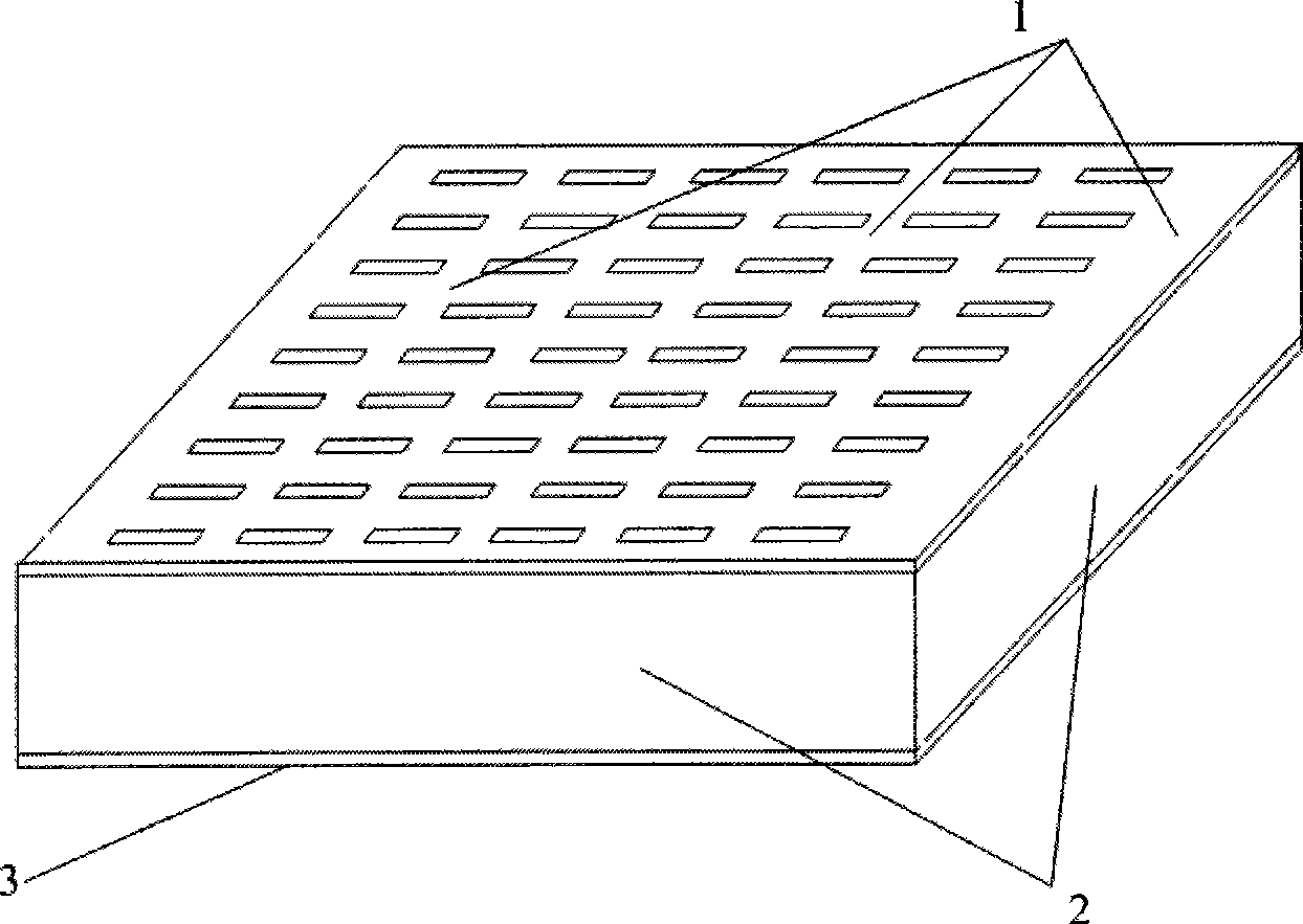
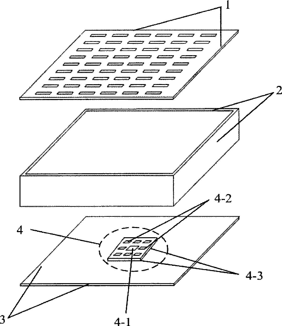
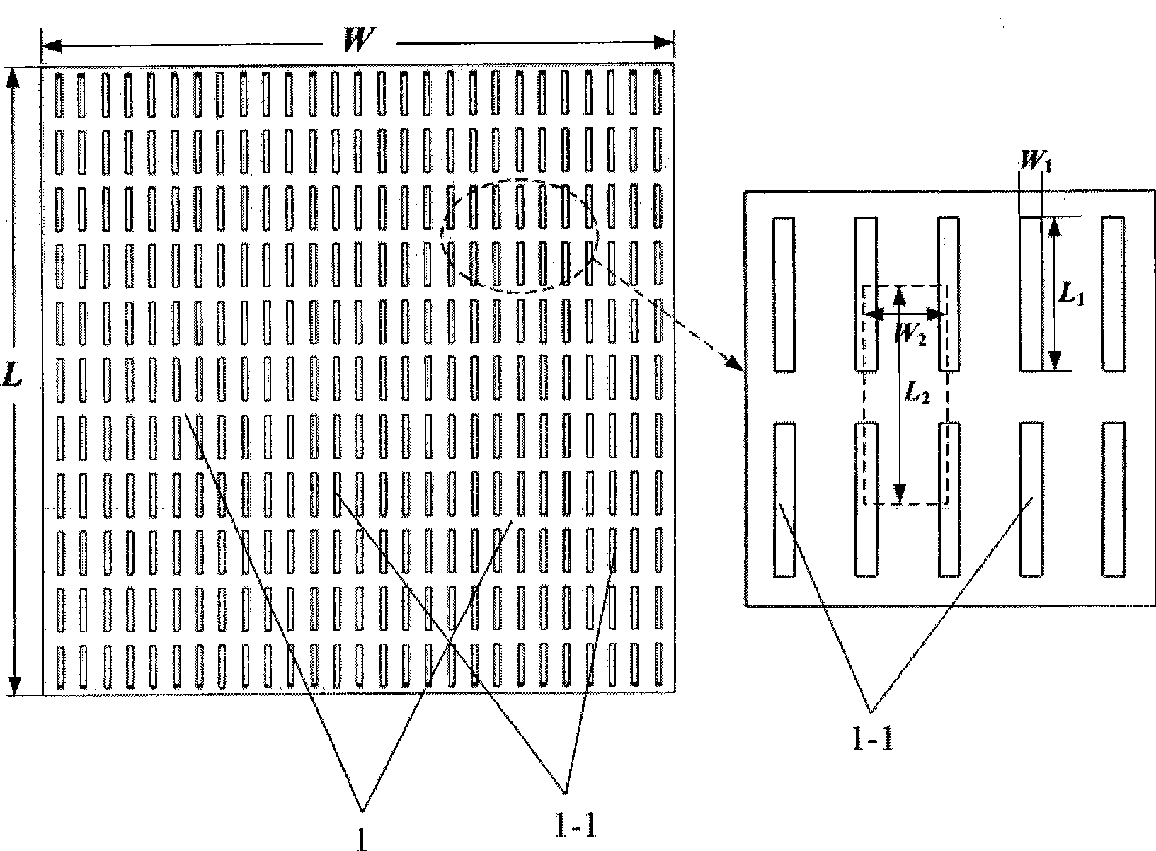
[0035] Adopt 1mm thick aluminum plate as the plate material of metal cover plate 1, metal side plate 2 and metal base plate 3; the peripheral dimensions of metal cover plate 1 and metal base plate 3 are the same: W=110mm, L=11mm; all on the metal cover plate 1 Gap unit 1-1 has the same size, and the structural parameter is W 1 = 1 mm, L 1 =7.5mm, W 2 = 4mm, L 2 = 10mm; the periphery of the metal side plate 2 is aligned with the metal cover plate 1 and the metal bottom plate 3 and forms a cavity, and the net height of the cavity is 11mm; the feed source patch 4-1 is printed on a layer with a thickness of 1mm and a relative dielectric constant On the dielectric substrate 4-3 of 2.2, the structural parameters of the dielectric substrate 4-3 are: W 3 =40mm, L 3 =40mm; the structural parameters of the feed patch 4-1 and the parasitic passive patch 4-2 are respectively taken as: W 4 =10mm, L 4 = 10mm, W 5 =7.5mm,L 5 =7.5mm, W 6 =13mm,L 6 =13mm; the feed connector 4-1-1 ado...


PUM


Abstract

A high-gain low-profile null feed array antenna comprises a metal cover plate, a metal side plate, a metal bottom plate and a feed source. The metal cover plate locates at the upper part, the metal bottom plate locates at the lower part and the metal side plate locates at the middle part; the metal cover plate, the metal bottom plate and the metal side plate are connected with each other to form a cavity in which the feed source is arranged; the metal cover plate is a metal flat plate which is provided with a group of gap units arranged periodically; the feed source comprises a feeding patch located in the middle of the housing and a group of passive parasitized patches around; the feeding patch and the parasitized patch are printed on the upper surface of a same dielectric substrate; the lower surface of the dielectric substrate is attached on the upper surface of the metal bottom plate; and the feeding patch is activated by a cable through a radio frequency coaxial joint. The antenna has the advantages of simple feeding, high gain of more than 20dBi, high caliber efficiency of more than 60 percent and low cost.

Description

technical field [0001] The invention relates to a high-gain antenna, in particular to a metal resonant cavity high-gain antenna. Background technique [0002] At present, there are mainly two types of high-gain antennas, one is an array antenna, and the other is a reflector antenna. [0003] The array antenna excites multiple radiating elements according to a certain amplitude and phase distribution to achieve high gain, and the excitation amplitude and phase of each radiating element are realized by the feed network. Generally, the higher the antenna gain requirement, the more the number of radiating elements required, resulting in more complex feeding network. On the one hand, the complex feed network will increase the difficulty of electrical design and physical layout. On the other hand, the feed loss will reduce the efficiency of the array antenna, especially in the high frequency band, which is so severe that it is no longer practical. [0004] The reflector antenna ...

Claims


Application Information

Patent Timeline
Patent Type & Authority Applications(China)
IPC IPC(8): H01Q13/08H01Q13/18
Inventor 章文勋吴知航
Owner SOUTHEAST UNIV
Why Eureka
Try Eureka