
Gap adjusting device used for adjusting grain size of bone cement

A gap adjustment device and technology of bone slime machine, applied in application, preparation of animal glue or gelatin, food science, etc., can solve problems such as reducing production efficiency of bone slime machine, inability to realize gap adjustment function, and difficulty in manufacturing large threads, etc. Achieve the effect of reliable and convenient gap adjustment, simple structure and simple installation

Active Publication Date: 2009-10-07
青岛市城阳区海天水产加工厂
View PDF0 Cites 1 Cited by
  • Summary
  • Abstract
  • Description
  • Claims
  • Application Information

AI Technical Summary

Problems solved by technology

But at present, some bone clay machines do not have any device for adjusting the gap, so this kind of bone clay machine cannot realize the gap adjustment function. Only when the grinding head is worn out, it is possible to adjust the gap between the dynamic grinding and the static grinding. In addition, most of the gap adjusting devices in the existing bone clay machines use the fixed grinding and the large thread on the machine body to adjust the gap between the fixed grinding and the dynamic grinding, but it is difficult to manufacture the large thread, and it is difficult to use it to adjust the gap , the adjustment process is cumbersome, the adjustment accuracy is low, and it is very heavy, which reduces the production efficiency of the bone clay machine

Method used


Image

  • Gap adjusting device used for adjusting grain size of bone cement
  • Gap adjusting device used for adjusting grain size of bone cement

Examples


Embodiment Construction

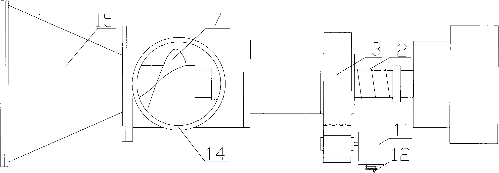
[0012] As shown in the figure, the shaft is in a non-working state. The left end of rotating shaft 1 is fixedly provided with inner cone 6, i.e. dynamic mill, rotating shaft 1 drives inner cone 6 to move, and outer cone is arranged on the outside of inner cone 6 and is fixed on housing 15. The middle position of rotating shaft 1 is provided with externally threaded shaft sleeve 4, and externally threaded shaft sleeve 4 slides on rotating shaft 1, and its outer surface is provided with screw thread, and the outer surface of externally threaded shaft sleeve 4 is spun into gear 3, and the inner surface of gear 3 The surface is provided with threads that mesh with the externally threaded bushing 4, that is, the gear 3 and the externally threaded bushing 4 are threadedly connected. The gear 3 is meshed with the gear 10 for transmission, and the gear 10 is fixed on the rotating mechanism 11 . By manually turning the adjusting handle 12 on the rotating mechanism 11, the gear 10 is r...


PUM


Abstract

The invention relates to a crusher, in particular to a gap adjusting device used for adjusting grain size of bone cement in a bone cement machine for carrying out processing animal bone. The gap adjusting device overcomes the defects that the manufacture of the gap adjusting device of movable grinding and fine grinding in the existing bone cement machine is difficult, the adjusting procedure is complex and the adjusting precision is low. The invention provides a gap adjusting device used for controlling the grain size of grinded paste of the bone cement, comprising a rotating shaft, an inner cone and an outer cone; wherein the inner cone body is fixed on the rotating shaft; the outer cone is fixed on a shell outside thereof; wherein the central part of the rotating shaft is provided with an axial transmission mechanism; one side of the transmission mechanism is connected with a spring, and the other side thereof is provided with a shaft sleeve with the T-shaped section; one end of the spring is connected with the axial transmission mechanism and the other end thereof is fixed on the rotating shaft; one end with larger diameter in the T-shaped shaft sleeve faces one side of the cone body and supports on the boss of the rotating shaft and the other corresponding end is adjacent to an axial transmission structure. The gap adjusting device has simple structure and convenient installation; when in use, the device has little mechanical friction resistance, precise gas adjustment quantity, convenient and reliable gap adjustment and no need of stopping the machine in the adjustment process.

Description

technical field [0001] The invention relates to a pulverizer, in particular to a gap adjustment device for adjusting the grain size of bone mud in a bone mud machine for processing animal bones. Background technique [0002] In the process of crushing animal bones with a bone slime machine, the granularity of the bone slime formed after crushing needs to be strictly controlled according to market demand, which is generally achieved by adjusting the gap between the dynamic mill and the static grinder. But at present, some bone clay machines do not have any device for adjusting the gap, so this kind of bone clay machine cannot realize the gap adjustment function. Only when the grinding head is worn out, it is possible to adjust the gap between the dynamic grinding and the static grinding. In addition, most of the gap adjusting devices in the existing bone clay machines use the fixed grinding and the large thread on the machine body to adjust the gap between the fixed grinding ...

Claims


Application Information

Patent Timeline
Patent Type & Authority Applications(China)
IPC IPC(8): A23L1/312A23K1/10C09H1/02A23L13/20
Inventor 招作胜招雷纪淑华
Owner 青岛市城阳区海天水产加工厂
Learn More