A safety protecting work trolley for chamber

A safety protection and workbench technology, which is applied in underground chambers, shaft linings, tunnel linings, etc., can solve the problems of low safety protection level, large operation risks, complex and changeable excavation working faces, etc., and achieve high safety protection design. level, improve safety protection ability, and improve the effect of ground adaptability

Active Publication Date: 2009-10-07
SINOHYDRO BUREAU 7 CO LTD
View PDF0 Cites 19 Cited by
  • Summary
  • Abstract
  • Description
  • Claims
  • Application Information

AI Technical Summary

Problems solved by technology

[0002] The excavation face of underground caverns in large-scale hydropower projects is complex and changeable, and there are great operational risks
At present, even in the excavation of underground caverns in large-scale hydropower projects where construction mechanization is becoming a trend, rock drilling rigs, bolting rigs, and shotcrete rigs cannot cover all the working surfaces of all caverns. The construction of scaffolding and steel mesh still has to be completed manually, so the design and manufacture of construction facilities and equipment for cavern manual work is common in engineering
Existing construction facilities and devices such as trolleys for cavern operations are generally only considered as a temporary facility or device (temporary workbench), which is temporarily fabricated for a specific cavern or specific requirements, and most of them are local materials. Temporary construction, without in-depth and comprehensive research on the safety risks and operational requirements of the construction of the newly dug cavern, the design is random, the structure is thin, the function is single, and the transfer is difficult. There are technical defects such as low safety protection level and poor construction efficiency to varying degrees.

Method used


Image

  • A safety protecting work trolley for chamber
  • A safety protecting work trolley for chamber
  • A safety protecting work trolley for chamber

Examples


Embodiment Construction

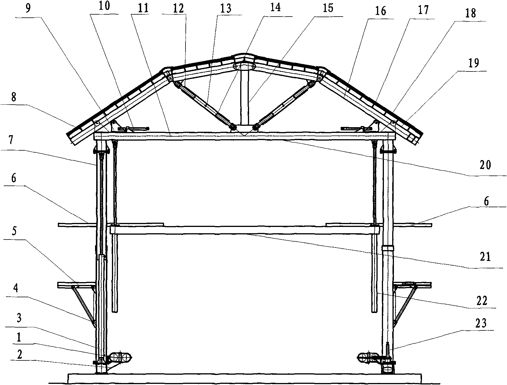
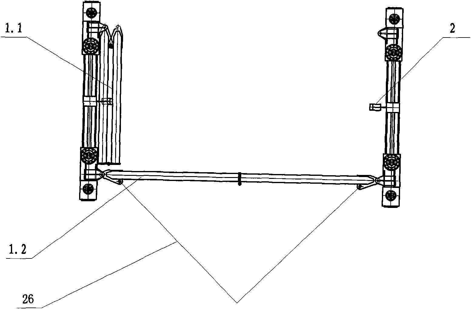
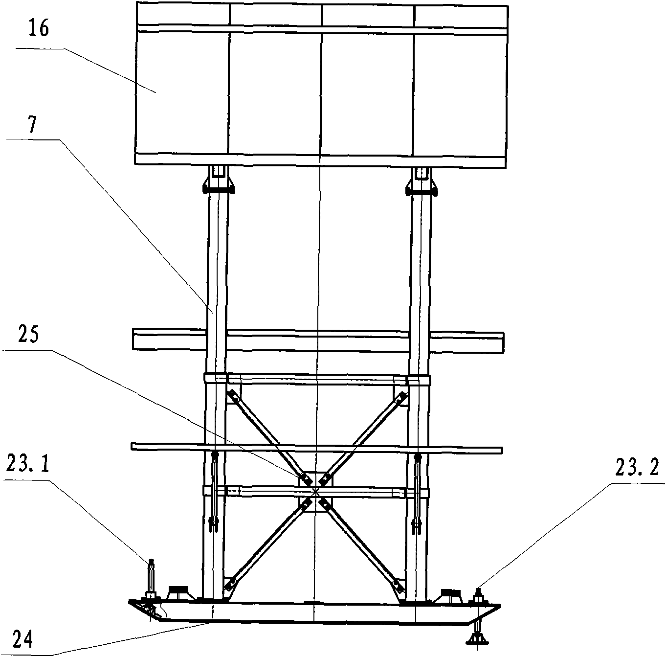
[0014] see Figure 1-Figure 4 , the present invention includes a protective shed 16, a work platform, an adjustment device and a mobile device, and the protective shed 16 is supported on the mobile device by a column 7. Its key technology is that the column 7 is a sleeve-type column, which is sheathed together by two pipe columns inside and outside, and the column lifting oil cylinder 3 is installed in the middle of the pipe column. The protective shed 16 is mainly composed of a protective roof truss and an expanded metal mesh 17. The protective roof truss includes a horizontal bar 11, a vertical bar 15 and an oblique bar 18. The horizontal bar 11 is connected end to end and fixed on the top of the column 7, and two of them are parallel to each other. The middle part of 11 fixes vertical bar 15 respectively, and oblique bar 18 is installed respectively between the top of vertical bar and the two ends of horizontal bar, constitutes the protective roof truss with symmetrical slo...


PUM


Abstract

The invention provides a safety protecting work trolley for chamber, belonging to the large water-power engineering underground chamber excavating safety protecting instrument, comprising a protecting shed, a working platform, an adjusting device and a moving device, wherein the protecting shed is composed of a protecting roof truss and a steel plate net; the protecting roof truss comprises a level rod, a vertical rod and a bevel rod; the head and tail of the level rod are connected and fixed to the top end of the upright rod; the vertical rod is fixed between two mutually parallel level rods; the bevel rod is mounted between the top end of the vertical rod and two ends of the level rod so as to form the protecting roof truss with symmetrical slopes. The working platform comprises an upper platform, a middle platform and an extension platform; the upper platform is set on the level rod; two ends of the middle platform are provided with platform lifting oil cylinders; the piston rods of the platform lifting oil cylinders are mounted at two ends of the upper platform. The invention is fit for the full process of excavating and supporting chamber; the invention has multiple suitability and high safety protecting design level.

Description

technical field [0001] The utility model relates to a cavern safety protection operation trolley, which belongs to a safety protection facility for the excavation of underground caverns in large-scale hydropower projects. Background technique [0002] The excavation face of underground caverns in large-scale hydropower projects is complex and changeable, and there are great operational risks. At present, even in the excavation of underground caverns in large-scale hydropower projects where construction mechanization is becoming a trend, rock drilling rigs, bolting rigs, and shotcrete rigs cannot cover all the working surfaces of all caverns. The construction of scaffolding and steel mesh still needs to be completed manually, so the design and manufacture of construction facilities and equipment for manual operations in caverns is common in engineering. Existing construction facilities and devices such as trolleys for cavern operations are generally only considered as a temp...

Claims


Application Information

Patent Timeline
Patent Type & Authority Applications(China)
IPC IPC(8): E21D11/04
Inventor 杨愚颜曦郭伦王德昌郑鹏鹏钱志刚
Owner SINOHYDRO BUREAU 7 CO LTD
Why Eureka
Try Eureka