Eureka AIR delivers breakthrough ideas for toughest innovation challenges, trusted by R&D personnel around the world.

Filter with variable bandwidth or wavelength interval based on chirp rate tuning of fiber bragg grating

A fiber grating, wavelength spacing technology, applied in the coupling of optical waveguides, optics, instruments, etc., can solve problems such as high cost, inconvenient operation, and complexity, and achieve the effect of improving accuracy

Inactive Publication Date: 2009-10-07
CHINA JILIANG UNIV
View PDF0 Cites 6 Cited by
  • Summary
  • Abstract
  • Description
  • Claims
  • Application Information

AI Technical Summary

Problems solved by technology

At present, many techniques for changing the reflection bandwidth of fiber Bragg gratings through the chirp rate have been reported, and thermal, mechanical, electromagnetic and other methods have been used, but the dynamic range of the reflection bandwidth of fiber Bragg gratings obtained by these methods is usually small ( less than 5nm), some technical means are more complicated, resulting in inconvenient operation and high cost
In addition, there is a very serious deficiency: when the reflection bandwidth of the fiber grating is changed, the central wavelength and reflectivity are also changed, causing the working wavelength range and reflectivity of the filter to deviate from the actual needs after the bandwidth is adjusted.

Method used


Image

  • Filter with variable bandwidth or wavelength interval based on chirp rate tuning of fiber bragg grating
  • Filter with variable bandwidth or wavelength interval based on chirp rate tuning of fiber bragg grating
  • Filter with variable bandwidth or wavelength interval based on chirp rate tuning of fiber bragg grating

Examples


Embodiment Construction

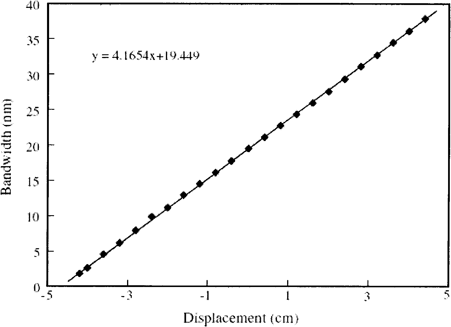
[0020] The following is attached figure 1 , 2 , 3, 4, 5 further describe the technical solution of the present invention.

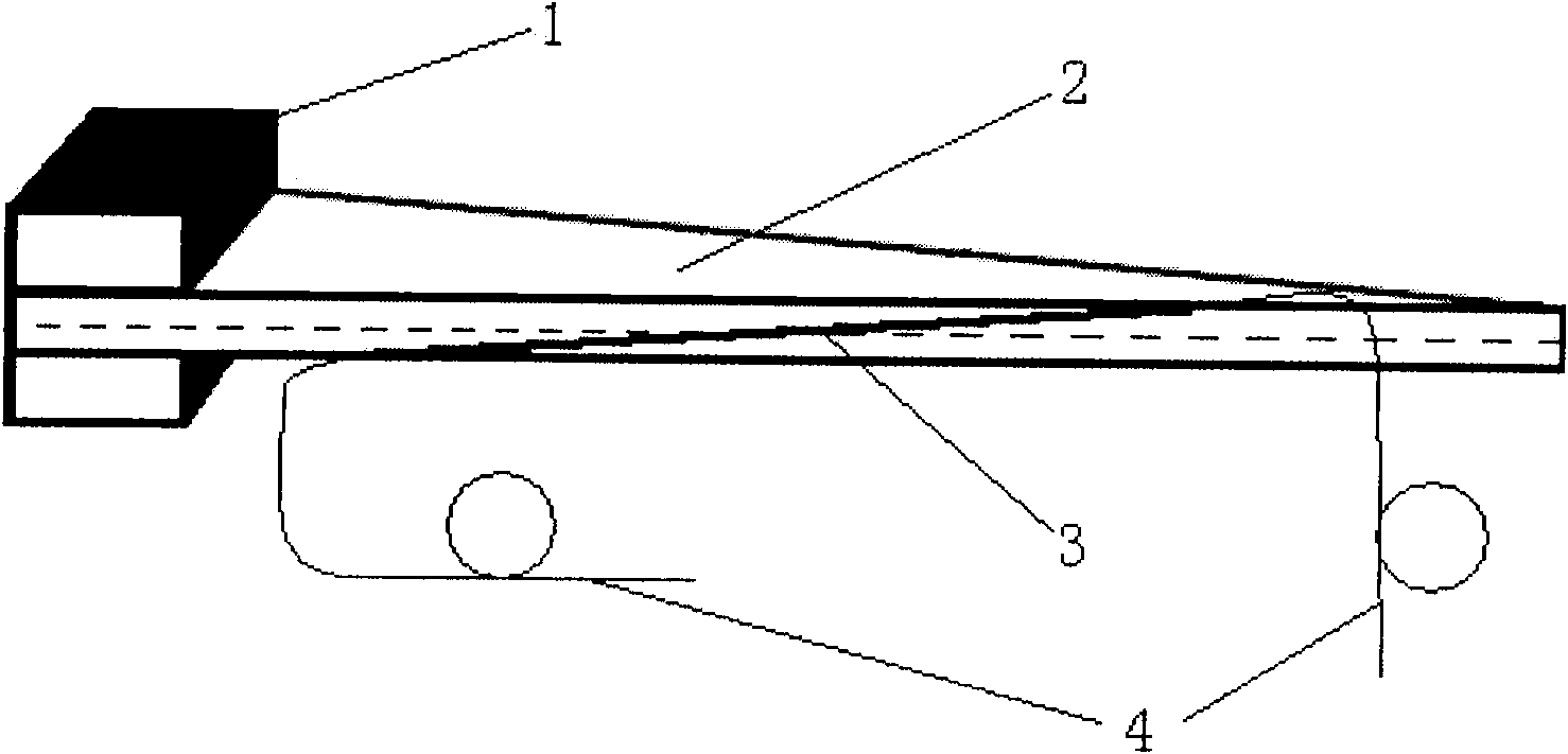
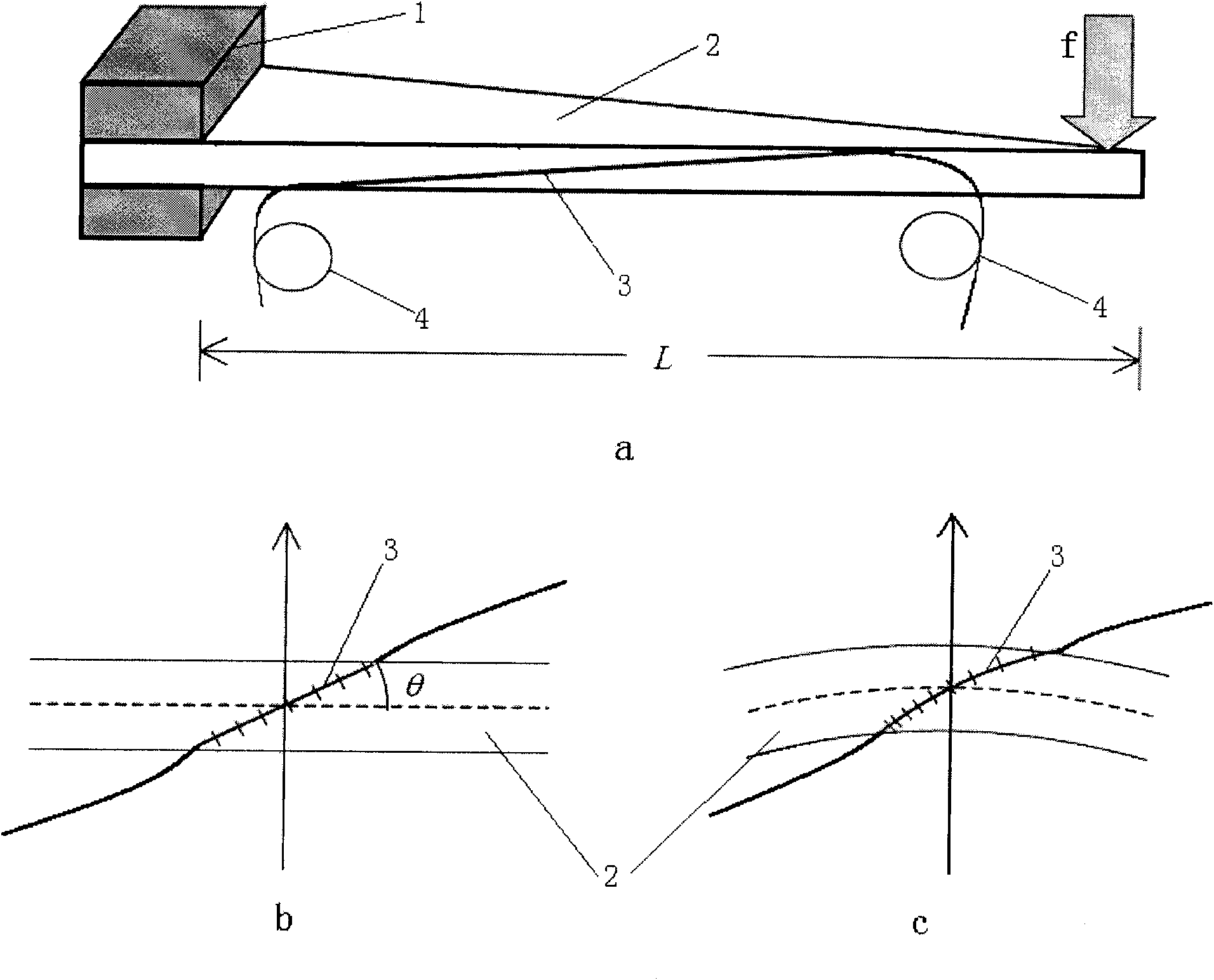
[0021] The present invention is based on the fiber grating chirp rate tuning bandwidth or wavelength interval variable filter structure diagram as shown in figure 1 shown. Paste the fiber grating 3 at an angle of 3-45 degrees on the side of the right-angled triangular cantilever beam 2, make the midpoint of the fiber grating 3 coincide with the neutral plane, ensure that the maximum strain values ​​at both ends of the fiber grating 3 are equal, and make the tuning range of the reflection spectrum bandwidth to reach maximum. If the center of the fiber grating 3 does not coincide with the neutral plane, the longer side of the fiber grating will be damaged first due to excessive strain.

[0022] figure 2 It is the schematic diagram of the fiber grating chirp rate tuning filter. In the figure, the force on the free end produces a certain displacement, w...


PUM


Abstract

The invention provides a filter with variable bandwidth or wavelength interval based on chirp rate tuning of fiber bragg grating belongs to optical fiber filter technology field, relates to fiber bragg grating and multiplex optical fiber communication system field. The filter applies strength cantilever girder (2) turning structure of right triangle, the cantilever girder (2) is fixed through splint (1), chirp fiber bragg grating or sampling chirp fiber bragg grating (3) is sticked on side surface of right angle edge in the cantilever girder (2) inclining for 3 to 45 DEG. Applying force or deflection along the vetical direction of free end of the cantilever girder (2), to make the cantilever girder (2) bend for changing chirp rate of the chirp fiber bragg grating (3), and finally reflection peak interval of the sampling chirp fiber bragg grating or reflection spectrum bandwidth of the chirp fiber bragg grating is changed, so as to achieve effect of selecting reflection filter of specific wavelength or wavelength range. The filter has advantages of large bandwidth turning range, high precision, simple structure, low cost, and the filter is siutable for various optical fiber network system especially wavelength division multiplexing system.

Description

technical field [0001] The invention belongs to the field of optical fiber filters, and in particular relates to a variable bandwidth or wavelength interval filter based on fiber grating chirp rate tuning, which is especially suitable for reflection band rejection and wavelength division multiplexing optical fiber communication systems. Background technique [0002] As an excellent filter inherently compatible with current fiber optic networks, fiber Bragg grating filters have been widely studied. Due to their unique filtering characteristics and versatility, they have been widely used in the fields of fiber optic communication and fiber optic sensing. A large number of applications. Because the central wavelength of the fiber grating is sensitive to strain and temperature changes, it can be used as a wavelength tunable filter. In addition, a filter with tunable reflection bandwidth can be obtained by changing the strain or temperature along the fiber grating with a certain...

Claims


Application Information

Patent Timeline
IPC IPC(8): G02B26/00G02B6/34
Inventor 董新永周文俊赵春柳龚华平裘燕青刘红林
Owner CHINA JILIANG UNIV
Why Eureka
Eureka Blog
Learn More