Battery module, electric storage device and electric system

一种电池模块、电池的技术,应用在输出功率的转换装置、二次电池、电池温度控制等方向,达到降低温度上升、降低充放电量和寿命的波动、降低压力损失的效果

Active Publication Date: 2009-10-07
NIPPON AUTOMOTIVE ENERGY CO LTD
View PDF2 Cites 36 Cited by
  • Summary
  • Abstract
  • Description
  • Claims
  • Application Information

AI Technical Summary

Problems solved by technology

However, the background art is an effective method for an electric storage device where the size of the battery module is not restricted, but it is not necessarily effective for an electric storage device where the size of the battery module is restricted, such as an electric storage device installed in a small storage space such as an automobile. method

Method used


Image

  • Battery module, electric storage device and electric system
  • Battery module, electric storage device and electric system
  • Battery module, electric storage device and electric system

Examples


Embodiment 1

[0063] according to Figure 1-8 The first embodiment of the present invention will be described.

[0064] First, use Image 6 The configuration of an on-vehicle motor system (motor drive system) will be described.

[0065] The vehicle-mounted motor system of this embodiment drives the motor generator 200, which is a three-phase AC synchronous machine, as a motor when the vehicle is in an operation mode that requires rotational power, such as when the vehicle is towed or when the engine that is an internal combustion engine is started. Rotational power is supplied to driven bodies such as wheels and an engine. Therefore, the vehicle-mounted motor system of this embodiment outputs DC power from the power storage device 100, which is the vehicle-mounted power supply, and converts the output DC power into a three-phase AC power through the power conversion device, namely, an inverter device 300, and converts the converted three-phase AC power into a three-phase AC power. AC pow...

Embodiment 2

[0207] according to Figure 9 A second embodiment of the present invention will be described.

[0208] In the first embodiment, a cylindrical (column) shape was used as the lithium cell 11, but in this embodiment, a square cylinder (square column) shape may also be used. The length of one side in the cross-section in the short-side direction of the lithium cell 11 is equal to the diameter D of the cylindrical lithium cell 11 in the preceding example.

[0209] The structure other than that is completely the same as that of the first embodiment. Therefore, the same reference numerals as those in the first embodiment are attached to the same structures as those in the first embodiment, and description thereof will be omitted.

[0210] According to the present embodiment described above, the same effect as that of the first embodiment can be achieved.

Embodiment 3

[0212] according to Figure 10 A third embodiment of the present invention will be described.

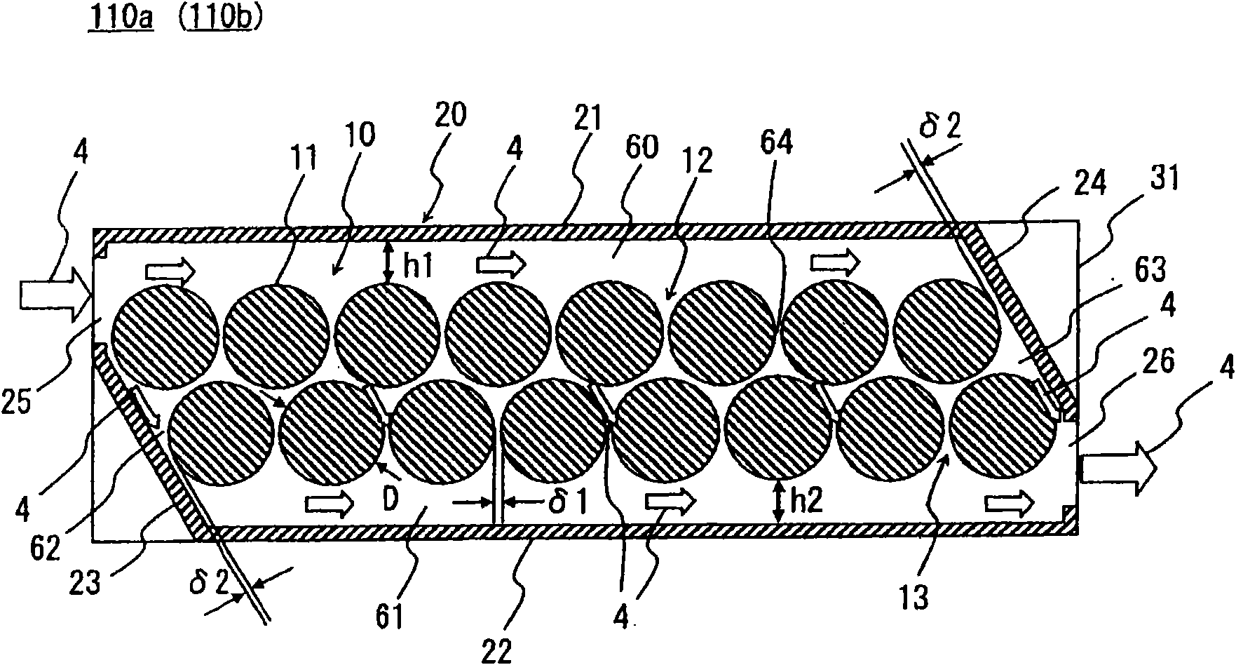
[0213] This embodiment is an improved example of the first embodiment, and the height of the outlet-side flow path 61, that is, from the position closest to the outlet flow-path forming plate 22 side of the lithium cells 11 constituting the second cell row 13 to the outlet flow path The height h2 in the height direction of the inner wall surface of the channel forming plate 22 is greater than the height of the inlet side flow channel 60 , that is, from the position closest to the inlet channel forming plate 21 side of the lithium cells 11 constituting the first cell row 12 to the inlet. Height h1 in the height direction of the inner wall surface of the flow path forming plate 21 . Therefore, the dimensional ratio of the height h2 of the outlet-side channel 61 to the diameter D of the lithium cell is larger than the dimensional ratio of the height h1 of the inlet-side channel 60 to ...


PUM


Abstract

A battery module (110) is provided with a battery pack (10) which configures a plurality of single lithium batteries to at least two segments and a casing (20) for holding the single lithium batteries, wherein, an inlet side flowpath (60) and an outlet side flowpath (61) are staggered in the height direction of the casing (20). Furthermore a height h1 of the inlet side flowpath (60) and a height h2 of the outlet side flowpath (61) are equal. Furthermore a clearance delta1 between the single lithium batteries (11) and a clearance delta2 between single lithium batteries (11) at two ends of each single battery row and the casing (20) are set to an approximate same dimension. The flowing direction of the cooling medium (4) which is introduced into the inlet side flowpath (60) is shunt to the side of the inlet side flowpath (60) and the clearance delta2. According to the structure, each single lithium battery (11) can be distributed with the cooling medium (4) with uniform flow capacity for cooling each single lithium battery (11).

Description

technical field [0001] The present invention relates to a technology related to a battery module having a plurality of cells, an electrical storage device having the battery module, and a motor system, and particularly relates to a technology for improving the cooling performance of the cells. Background technique [0002] As the background art related to the cooling technique of a single cell, for example, what is disclosed by patent document 1, 2 is known. [0003] Patent Document 1 discloses a technique of arranging a plurality of battery rows in which a plurality of cylindrical single cells are arranged in parallel, aligning the respective axis directions, and forming a main refrigerant between the battery holding part partition wall and the battery row. and a secondary refrigerant flow path is formed between the battery holding parts in the horizontal direction, and the refrigerant is supplied to the direction along the battery row to allow the main refrigerant flow pat...

Claims


Application Information

Patent Timeline
Patent Type & Authority Applications(China)
IPC IPC(8): H01M10/00H01M10/36H01M10/40H01M10/50H01M10/42H02M1/00H01M10/613H01M2/10H01M10/60H01M10/617H01M10/625H01M10/643H01M10/651H01M10/6563H01M10/6566H01M10/658
CPCY02E60/12H01M10/5004H01M10/5016H01M10/503H01M10/5067H01M10/5073H01M10/613H01M10/625H01M10/643H01M10/6563H01M10/6566Y02E60/10
Inventor 原田进大西益弘佐藤诚一鹤见芳久
Owner NIPPON AUTOMOTIVE ENERGY CO LTD
Why Eureka
Try Eureka