An electric motor control device and an electric motor control system

A control device and motor technology, applied in motor control, motor generator control, AC motor control, etc., can solve the problems of calculation error, excessive attenuation gain, low numerical dynamic range, etc., and achieve the effect of suppressing overflow calculation.

Active Publication Date: 2009-10-07
HITACHI IND EQUIP SYST CO LTD
View PDF2 Cites 7 Cited by
  • Summary
  • Abstract
  • Description
  • Claims
  • Application Information

AI Technical Summary

Problems solved by technology

[0008] In the technique of the UD decomposition algorithm, when the absolute value of the input signal given to the recognition operation is too large, overflow may occur in the recursive least squares operation
In particular, due to the low dynamic range of values ​​that can be represented by fixed decimal point operations, overflow is prone to occur in the case of performing recursive least squares
[0009] For this problem, the general solution is to put an attenuator (attenuation gain greater than 0 and less than 1) on the input part of the recursive least squares method, but there are the following problems: when the attenuation gain is too large (attenuation rate is small) , the recognition error increases due to overflow; the attenuation gain is too small (the attenuation rate is large), and the recognition error caused by the rounding error of the input signal increases
In addition, as another solution, although there is a simple method of using a limiter on the calculation result to avoid overflow, it will also cause calculation errors caused by saturation, resulting in a problem of low recognition accuracy

Method used


Image

  • An electric motor control device and an electric motor control system
  • An electric motor control device and an electric motor control system
  • An electric motor control device and an electric motor control system

Examples


no. 1 Embodiment approach

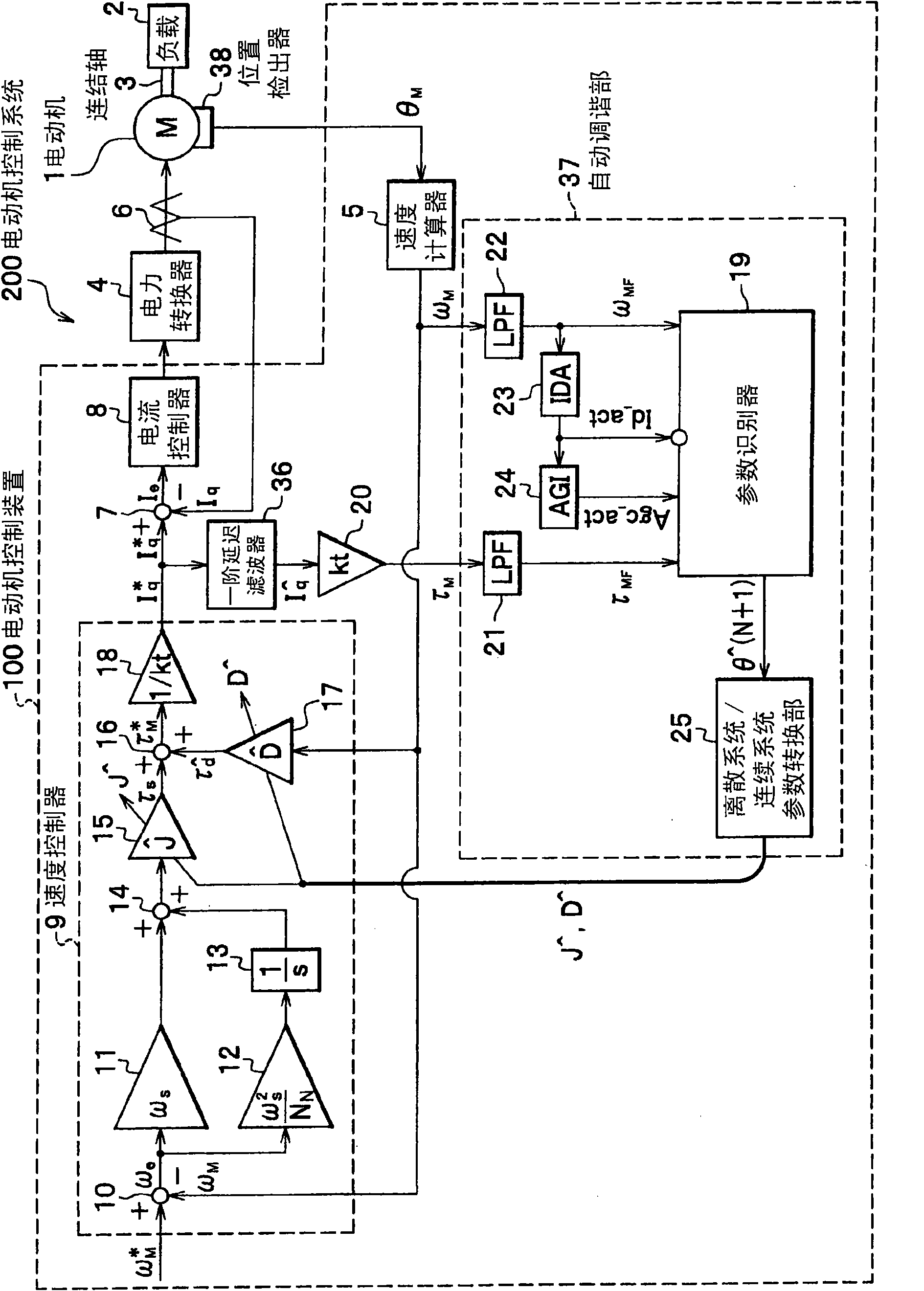
[0175] use figure 1 A configuration diagram of a motor control system as a first embodiment of the present invention will be described.

[0176] exist figure 1 Among them, the motor control system 200 includes: a motor 1; a load 2 driven by the motor 1 (a load to be driven); a connecting shaft 3 connecting the motor 1 and the load 2; a power converter 4 for driving the motor 1; On the rotating shaft, output the position detection value θ of the rotating shaft of the motor 1 M The position detector 38; the current detector 6 that detects the current flowing into the motor 1; and the motor control device 100.

[0177] The motor control device 100 includes: a speed calculator 5; a current controller 8; a first-order delay filter 36; a torque constant amplifier 20; an automatic tuning section 37; a discrete system / continuous system parameter conversion section 25; a speed controller 9; Subtractor 7, their functions are realized by computers such as CPU and programs. Furthermor...

no. 2 Embodiment approach

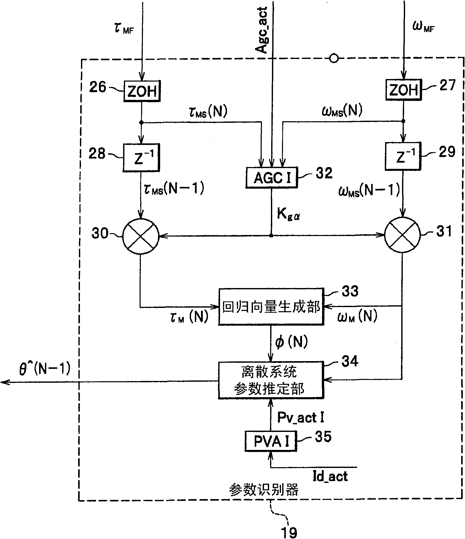
[0305] Next, use Figure 18 , the parameter recognizer according to the second embodiment of the present invention will be described. and figure 2 The parameter identifier 19 shown differs in that the attenuation gain Kgα Multiply this point with the regression vector. In addition, the configuration of the motor control system is the same as that of the first embodiment figure 1 same.

[0306] The regression vector generation unit 351 inputs τ according to the formula (62) MS (N) and ω MS (N), generate regression vector Φ * (N). Multiplier 353, the attenuation gain K outputted by automatic gain control section 352 (AGC2) gα and regression vector Φ * (N) are multiplied, and the operation result is output as a regression vector Φ(N). The multiplier 354 will attenuate the gain K gα with ω MS (N) are multiplied, and the operation result is taken as ω M (N) output.

[0307] The discrete system parameter estimation unit operation signal generator 355 (PVA2) outputs Id_...


PUM


Abstract

The invention provides an electric motor control device and sets best gain reduction for the input signals provided to the recognition operation. The invention comprises zero holding components (26, 27) for the periodical sampling and maintaining, delay components (28, 29) for the first sampling periodical delaying for the output signals of the zero holding components, multipliers (30, 31) for the reduction of the output signals of the delay components, a regression vector generation part (33) for the regression vector generation by adopting the output signals of the multipliers as the input, a discrete system parameter estimation part (34) for the discrete estimation of the parameter vectors by adopting the regression vector as the input and an automatic gain control part (32) which adopts the output signals of the zero holding components (26, 27) as the input signals and outputs the gain set values of the multipliers.

Description

technical field [0001] The invention relates to a motor control device and a motor control system for speed control by identifying parameters. Background technique [0002] As a motor control device used in industrial machinery (semiconductor manufacturing equipment, machine tools, injection molding machines), etc., a technique is known to identify the total moment of inertia, viscous friction coefficient, constant external disturbance torque, etc. during actual operation Mechanical system parameters, and use the identification results for the automatic setting of controller parameters such as speed controllers. For example, Patent Document 1 discloses a technique for identifying the above-mentioned mechanical system parameters by the recursive least square method using time-series data of each motor torque, acceleration, and motor speed during forward rotation and reverse rotation. [0003] In addition, as a more general automatic setting technique of control parameters, s...

Claims


Application Information

Patent Timeline
Patent Type & Authority Applications(China)
IPC IPC(8): H02P23/14H02P25/16H02P27/04H02P21/00H02P21/14H02P21/18H02P21/24H02P23/16H02P27/08H02P29/00
CPCH02P21/143G05B13/041H02P21/0003
Inventor 名仓宽和大桥敬典高野裕理
Owner HITACHI IND EQUIP SYST CO LTD
Why Eureka
Try Eureka