
Robot leg mechanism

A technology of a robot and a transmission mechanism, applied in the field of leg structure of humanoid robots, can solve the problems of increasing motion inertia, low rigidity, reducing driving capacity, etc., and achieves the effects of good processing and assembly manufacturability, strong bearing capacity and simple structure

Inactive Publication Date: 2009-10-14
ZHEJIANG UNIV OF TECH
View PDF0 Cites 7 Cited by
  • Summary
  • Abstract
  • Description
  • Claims
  • Application Information

AI Technical Summary

Problems solved by technology

[0002] Most anthropomorphic robots use series mechanism, which has the advantages of large working space, flexible movement and easy control, but there are also some shortcomings: 1. The quality of the lower driver becomes the load of the upper driver, thereby increasing the motion inertia and reducing the driving ability ; 2. For multi-rotational joints such as shoulder joints and hip joints, their motion functions are only comparable to those of humans in three specific directions (driver axes), and there are obvious decomposition movements in the other directions. Its flexibility and accuracy 3. Multi-rotation pair series joints occupy a large space and have low rigidity; 4. Limb functions are not complete. For example, the waist joint adopts single rotation pair series connection, compared with human waist joints. It is completely different. It can only partially complete the movement adjustment between the upper limbs and the lower limbs. It is not ideal for the functions of reasonably compensating the movement, adjusting the balance of the robot, completing the attitude change, and ensuring the stability of the robot.
Therefore, it is difficult to adapt to unstructured environmental pavement

Method used


Image

  • Robot leg mechanism

Examples


Embodiment Construction

[0018] With reference to accompanying drawing, further illustrate the present invention:

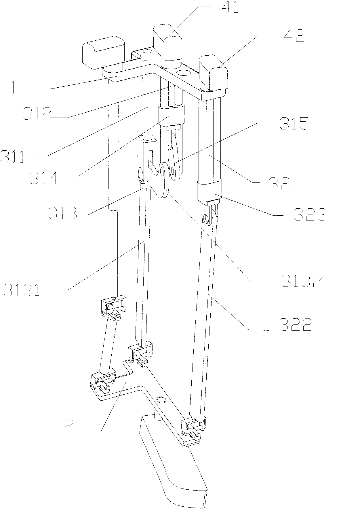
[0019] The robot leg mechanism includes a base 1 and a motion platform 2, and the base 1 is connected with the motion platform 2 through a transmission mechanism; the transmission mechanism includes motors 41, 42 fixed on the base 1 and connected with The motion unit connected with the motors 41 and 42;

[0020] The motion unit includes a first motion unit capable of swinging the robot leg mechanism backward and a second motion unit capable of pressing down or lifting the motion platform;

[0021] The first moving unit includes a support rod 311 whose top end is fixed on the base 1, connected with the first motor 41 to a first screw mechanism 312 and a hinged joint with the moving platform 2. The first fixed length rod 313; the first fixed length rod 313 includes a straight rod part 3131 and an outwardly protruding lug part 3132, and the support rod 311 is hinged with the described stra...


PUM


Abstract

A robot leg mechanism comprises a base and a moving platform, wherein the base is connected with the moving platform by a transmission mechanism; the transmission mechanism comprises a motor fixed on the base and a moving unit connected with the motor; the moving unit comprises a first moving unit which can lead the robot leg mechanism to swing backwards and a second moving unit which can lead the moving platform to be pressed downwards or lifted; the first moving unit comprises a supporting rod with the top end fixed on the base, a first screw rod mechanism connected with a first motor, and a first rod with constant length hinged with the moving platform; the first rod with constant length comprises a straight-rod part and a lug part protruding outwards, the supporting rod is hinged with the straight-rod part, and the first screw rod mechanism is hinged with the lug part; the second moving unit comprises a second screw rod mechanism connected with a second motor, and a second rod with constant length hinged with the moving platform, and the second screw rod mechanism is hinged with the second rod with constant length. The robot leg mechanism has the advantages of simple structure, strong bearing capability, small volume, and good processing and assembling technology.

Description

technical field [0001] The invention relates to a leg structure of a humanoid robot. Background technique [0002] Most of the anthropomorphic robots adopt series mechanism, which has the advantages of large working space, flexible movement and easy control, but there are also some shortcomings: 1. The quality of the lower driver becomes the load of the upper driver, thereby increasing the motion inertia and reducing the driving ability ; 2. For multi-rotational joints such as shoulder joints and hip joints, their motion functions are only comparable to those of humans in three specific directions (driver axes), and there are obvious decomposition movements in the other directions. Its flexibility and accuracy 3. Multi-rotation pair series joints occupy a large space and have low stiffness; 4. Limb functions are not complete. For example, the waist joint adopts a single rotation pair series connection, compared with human waist joints. It is completely different. It can onl...

Claims


Application Information

Patent Timeline
IPC IPC(8): B62D57/032
Inventor 李研彪计时鸣袁巧玲张利
Owner ZHEJIANG UNIV OF TECH
Learn More