
Intelligent lighting automatic detection and analysis system and detection method thereof

An automatic detection and analysis system technology, applied in the direction of optical instrument testing, measuring devices, testing optical performance, etc., can solve problems such as lack of detection

Active Publication Date: 2009-10-14
天津圣纳科技有限公司
View PDF0 Cites 21 Cited by
  • Summary
  • Abstract
  • Description
  • Claims
  • Application Information

AI Technical Summary

Problems solved by technology

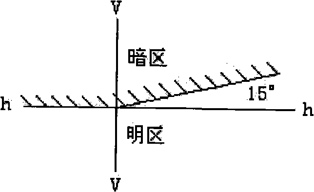
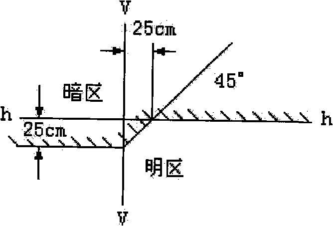
However, due to the shape of the visor and the installation position of the current low beam, there is often a shape that satisfies the light type. However, although the brightness at the upper left of the spot is weaker than that at the lower right, it still has a certain intensity. The driver will cause some bad effects, so it is very important to require a clear cut-off zone of low beam lights, but the current headlight detectors do not have the function of detecting this performance
[0009] In short, the current detector can only measure the height of the headlight, the light intensity of the high beam, the deflection of the spot center, and the inflection point of the low beam.

Method used


Image

  • Intelligent lighting automatic detection and analysis system and detection method thereof
  • Intelligent lighting automatic detection and analysis system and detection method thereof
  • Intelligent lighting automatic detection and analysis system and detection method thereof

Examples


Embodiment Construction

[0026] The specific implementation manners, structures, features and functions provided by the present invention will be described in detail below in conjunction with the accompanying drawings and preferred embodiments.

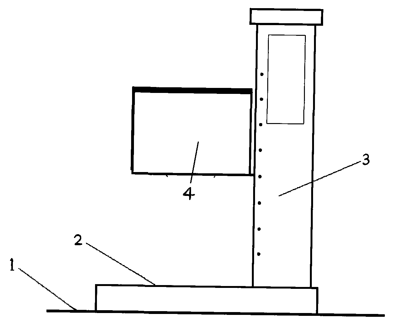
[0027] see Figure 2~3 , an intelligent lighting automatic detection and analysis system, comprising a guide rail 1, a base trolley 2, a column 3, a light receiving box 4, an optical system, a CCD camera, a single-chip processing system 10 and a DSP image processing system 11, and the base trolley is equipped with The guide rail and the column are installed on the base trolley, and the light receiving box is installed on the column. The light receiving box is equipped with a Finsier lens 5, two CCD cameras 6, 7, an imaging screen 8 and a light metering strong light battery sensor 9; the Fresnel lens It is used for high-beam or low-beam imaging. One of the CCD cameras 6 is used to aim at the luminous motor vehicle headlights; the other CCD camera 7 uses a high...


PUM


Abstract

The invention relates to an intelligent lighting automatic detection and analysis system and a detection method thereof. The intelligent lighting automatic detection and analysis system comprises a guide way, a base larry, an upright post, a photic box, an optical system, a CCD vidicon, a singlechip processing system and a DSP image processing system, wherein symmetry of high beam light spots is obtained from images photographed by the CCD vidicon in the photic box through pretreatment, isolux annulus extraction, isolux annulus centre calculation and symmetry check; and definition of low beam light spots on a dividing line of light and dark cutoff regions is obtained from the images through the pretreatment, low beam light and dark bend line extraction and light and dark dividing line bright band width calculation. The invention detects the lighting quality of high beam and low beam by adopting the method of judging the symmetry of the high beam light spots with the relative average offset of isolux annuluscentre coordinates to the centre of the light spots and the calculation method, and the method of judging definition of the low beam light spots on the light and dark bend positions with size of band width of the bright band of the images above the bend line and the calculation method of the band width of the bright band.

Description

technical field [0001] The invention belongs to the field of special testing equipment, and relates to an intelligent light automatic detection and analysis system and a detection method thereof, which can judge the symmetry of the light spot of the high beam of the automobile headlamp and determine the brightness and darkness at the inflection point of the low beam illumination of the automobile headlamp The clarity judgment of the cut-off area can detect the lighting quality of high beam and low beam, and provide detailed lamp spot data for lamp manufacturers, thereby providing a basis for improving the structure of the lamp. In addition, it can also be used to test the lighting quality of other lamps. Background technique [0002] The headlight is an important device for the car to provide road lighting for the driver at night or in the case of low visibility, and it is also a light signal device for the driver to warn and communicate. Therefore, the headlight must have s...

Claims


Application Information

Patent Timeline
Patent Type & Authority Applications(China)
IPC IPC(8): G01M11/06G01M11/00
Inventor 魏所库孙立新
Owner 天津圣纳科技有限公司
Learn More