
Cross transpose fully low pressure low temperature drift cold scanning probe microscope body

A scanning probe and low-temperature drift technology, applied in microscopes, measuring devices, instruments, etc., can solve the problems of noise, speed, accuracy, and power consumption that are not as good as low-voltage operational amplifiers, and are expensive, and achieve temperature drift suppression, low price, and The effect of high temperature stability

Inactive Publication Date: 2009-10-14
UNIV OF SCI & TECH OF CHINA
View PDF0 Cites 7 Cited by
  • Summary
  • Abstract
  • Description
  • Claims
  • Application Information

AI Technical Summary

Problems solved by technology

[0003] The above-mentioned dependence on high voltage greater than 18V leads to the need to use high-voltage operational amplifiers for control circuits, and high-voltage operational amplifiers are generally far inferior to low-voltage operational amplifiers in terms of noise, speed, accuracy, power consumption, etc., and the price is very expensive. many

Method used


Image

  • Cross transpose fully low pressure low temperature drift cold scanning probe microscope body
  • Cross transpose fully low pressure low temperature drift cold scanning probe microscope body
  • Cross transpose fully low pressure low temperature drift cold scanning probe microscope body

Examples


Embodiment 1

[0030] Example 1: Double piezoelectric tube vertical and horizontal transposition full low-voltage low-temperature drift scanning probe microscope mirror body

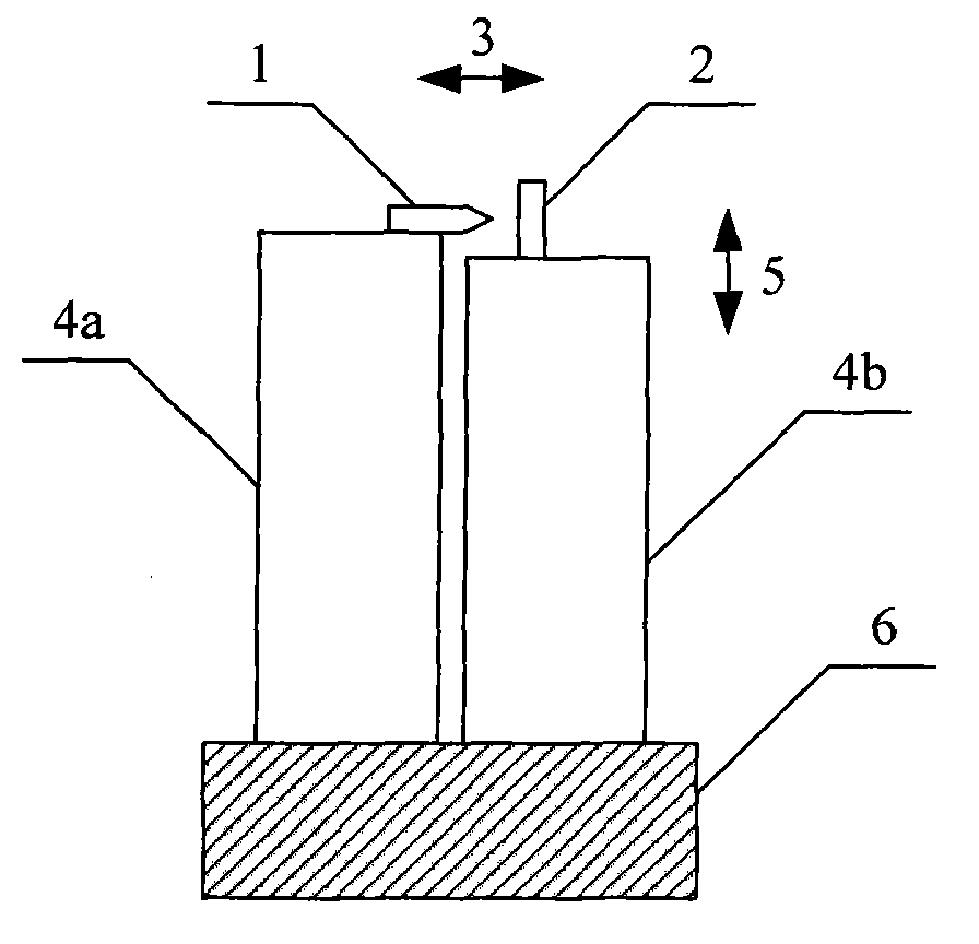
[0031] figure 1 It is a schematic diagram of the basic structure of the mirror body of the double piezoelectric tube type vertical and horizontal transposition full low-voltage low-temperature drift scanning probe microscope. Two piezoelectric tubes 4a, 4b stand side by side and are fixed on the base 6, the probe 1 and the sample 2 are respectively arranged at the free ends of the two piezoelectric tubes, and the gap between the probe 1 and the sample 2 is adjusted The direction 3 is perpendicular to the axial direction 5 of the two piezoelectric tubes, and the two piezoelectric tubes at least include one X positioning, one Y positioning and one Z positioning integrally or separately.

[0032] When working, since the first piezoelectric tube 4a and the second piezoelectric tube 4b include at least one X positioning, ...

Embodiment 2

[0036] Example 2: Single piezoelectric tube vertically and horizontally transposed full low-voltage low-temperature drift scanning probe microscope mirror body

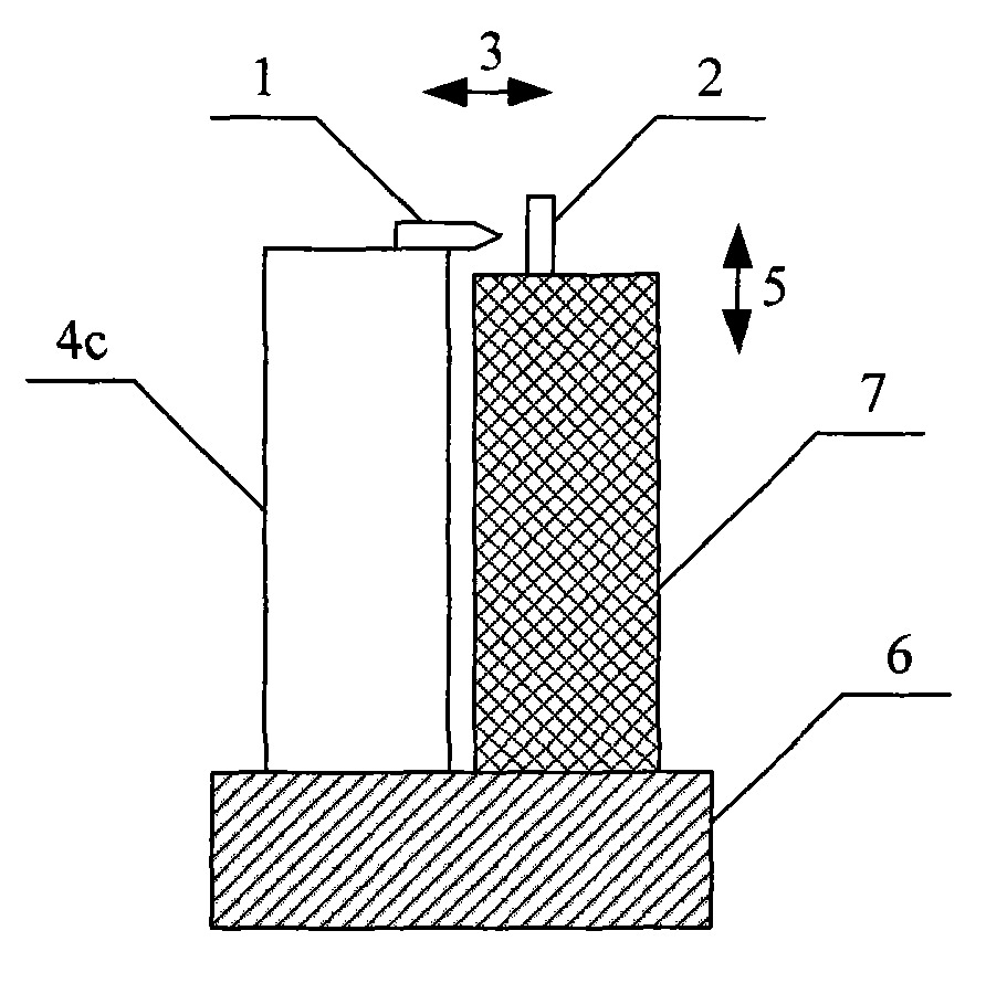
[0037]For the two piezoelectric tubes in Embodiment 1, if one of them is selected as an XYZ positioning piezoelectric tube, the other piezoelectric tube does not need to have a positioning function, and can be replaced by any vertical rod 7 to form a single piezoelectric tube type vertical and horizontal rotation. Set full low-pressure low-temperature drift scanning probe microscope body, see attached figure 2 . The specific method is: the XYZ positioning piezoelectric tube 4c and the vertical rod 7 stand side by side and are fixed on the base 6, the probe 1 and the sample 2 are respectively arranged on the free ends of the XYZ positioning piezoelectric tube 4c and the vertical rod 8, and probe The positions of the needle 1 and the sample 2 can also be reversed, and the gap adjustment direction 3 between the probe 1...

Embodiment 3

[0039] Embodiment 3: A vertically and horizontally transposed full low-voltage low-temperature drift scanning probe microscope mirror body with an inertial stepping motor

[0040] A mass block can be added between the free end of the piezoelectric tube described in Embodiment 1-2 and the probe or sample arranged on it to form a probe-sample coarse approximation inertial stepping motor.


PUM


Abstract

The invention relates to a cross transpose fully low pressure low temperature drift cold scanning probe microscope body which comprises a probe, a sample, and two piezoelectric tubes that stand in parallel and are fixed on a base, wherein the probe and the sample are respectively arranged at free ends of the two piezoelectric tubes, the regulation direction of the space between the probe and the sample is vertical to the axis direction of the two piezoelectric tubes, and the two piezoelectric tubes at least comprise an X location, a Y location and a Z location which are integrally or detachably arranged. The invention improves the regulation range of the space between the probe and the sample through setting the regulation direction of the space between the probe and the sample to be vertical to the axial direction of the two piezoelectric tubes so as to realize that the function of crude approximation, fine approximation and imaging on a wavy surface by using high voltage more than 18V in the prior art can be realized under the condition of fully using low voltage less than 18V, and has higher heat stability.

Description

technical field [0001] The invention relates to a scanning probe microscope mirror body, in particular to a vertically and horizontally transposed full low-voltage low-temperature drift scanning probe microscope mirror body, specifically a method for adjusting the distance between a probe and a sample in the same direction as the axial direction of a piezoelectric tube. Vertical to improve the adjustment range of the probe-sample distance, so that the functions of rough approximation, fine approximation and imaging of large undulating surfaces can also be realized when using a low voltage of less than 18V in the past. , and a scanning probe microscope body with high thermal stability. Background technique [0002] The probe-sample rough approximation of the existing scanning probe microscope (SPM) generally uses piezoelectric motors, stepper motors or screw adjustments. Their step distance is large and the positioning repeatability is not ideal. After the rough approximation...

Claims


Application Information

Patent Timeline
Patent Type & Authority Applications(China)
IPC IPC(8): G01N13/10G02B21/00
Inventor 侯玉斌王霁晖陆轻铀
Owner UNIV OF SCI & TECH OF CHINA
Learn More