Manufacturing method of self-reset cable winding device

A cable winding and manufacturing method technology, which is applied to electrical components, antennas and other directions, can solve the problems of unable to achieve orderly movement of cables, and achieves the effect of simple structure, low manufacturing cost and solving cable damage.

Active Publication Date: 2009-10-14
NO 54 INST OF CHINA ELECTRONICS SCI & TECH GRP
View PDF0 Cites 3 Cited by
  • Summary
  • Abstract
  • Description
  • Claims
  • Application Information

AI Technical Summary

Problems solved by technology

If the axis of the rotary axis is not in the vertical or horizontal position, it must move around other axes, such as a polarized rotary axis. It not only rotates, but also tilts along with the pitch axis. The angle between the axis and the horizontal plane is changing, such a device cannot achieve orderly movement of the cable
In addition, for antennas installed on aircraft and other carriers, the inclination angle of the rotary axis will also change with the attitude of the carrier, and the orderly movement of the cables cannot be realized, and the requirements for cable winding in dynamic carriers cannot be met.

Method used


Image

  • Manufacturing method of self-reset cable winding device
  • Manufacturing method of self-reset cable winding device
  • Manufacturing method of self-reset cable winding device

Examples


Embodiment Construction

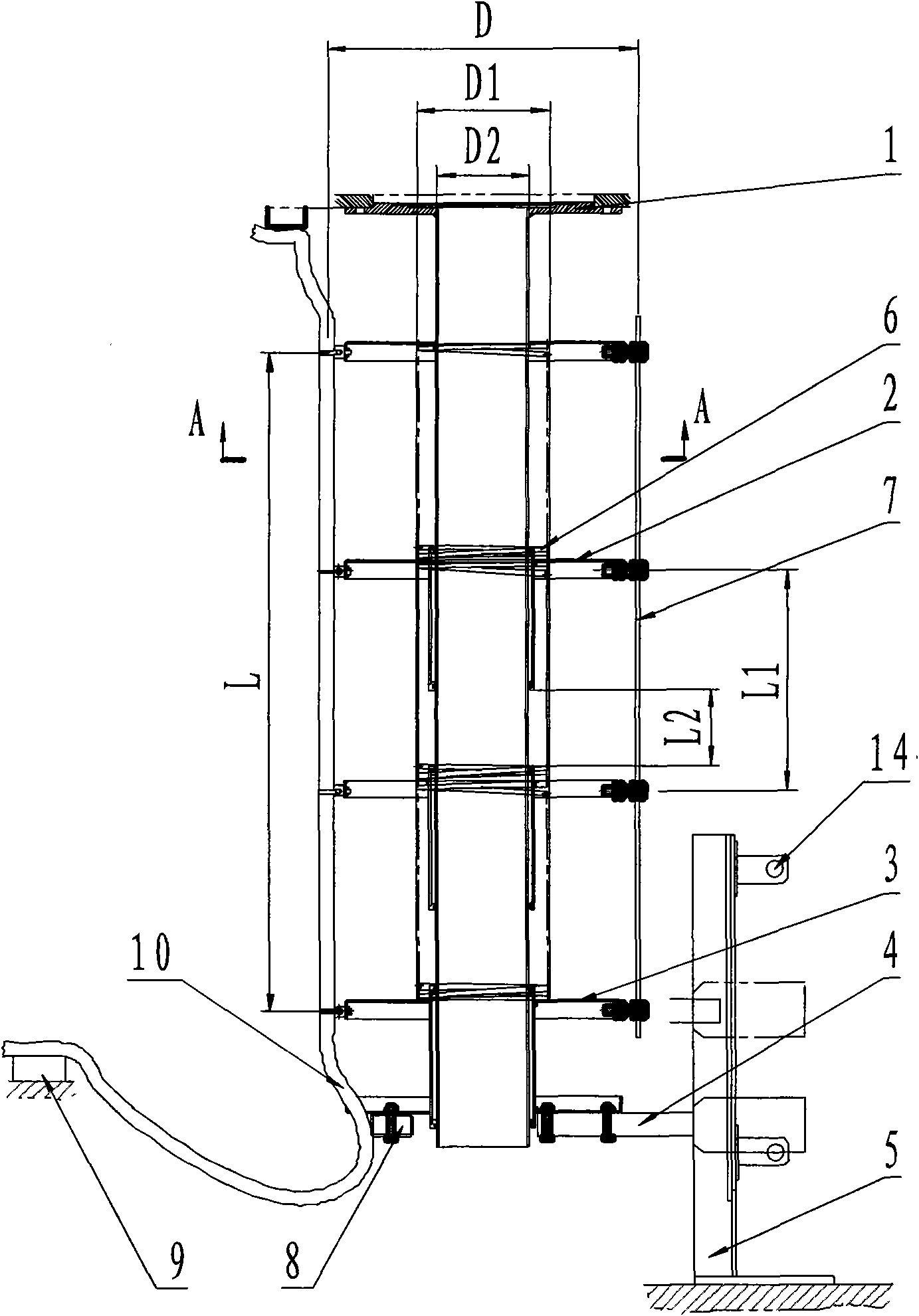
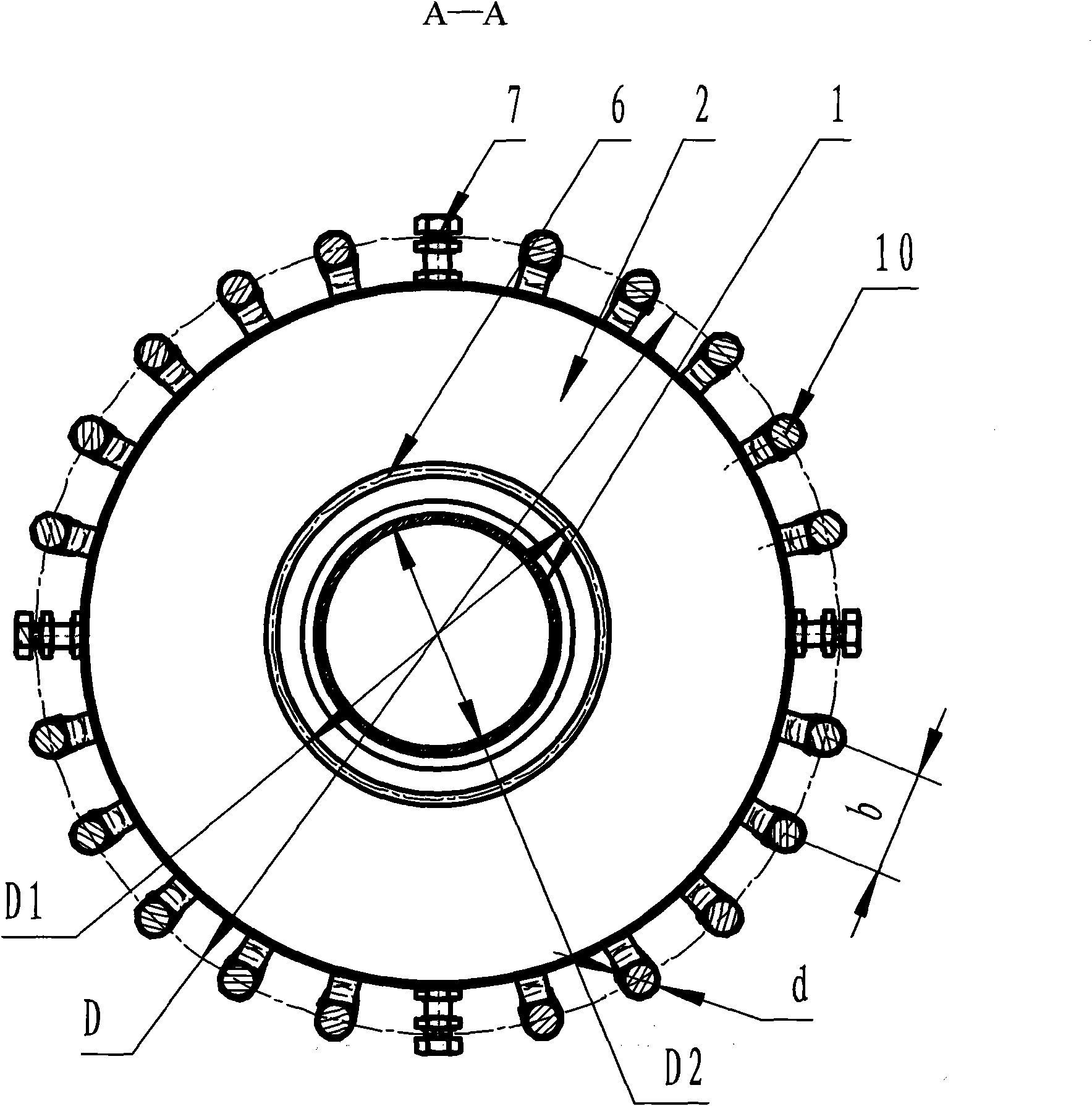
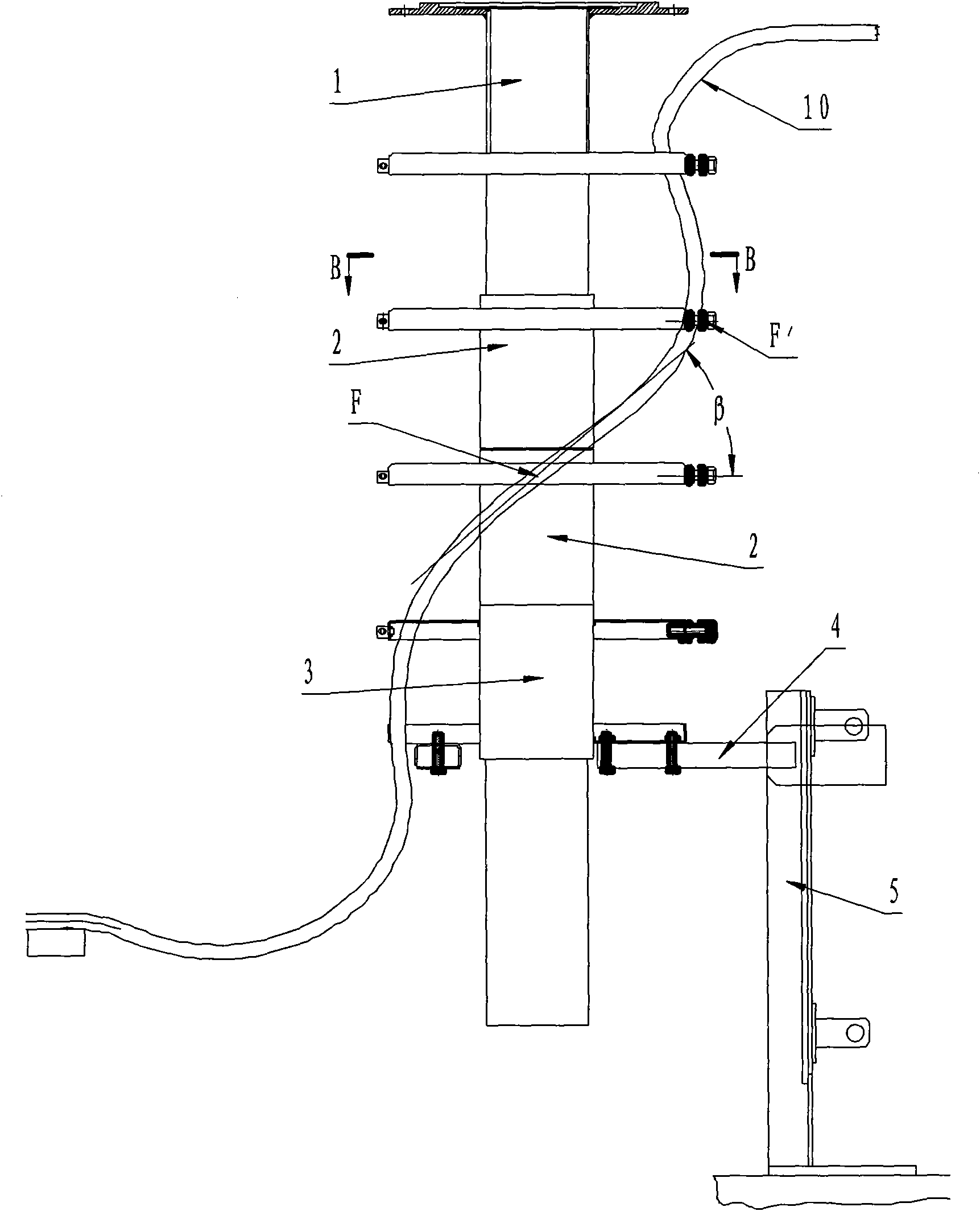
[0029] Refer to Figure 1 to Figure 4 , The present invention consists of a slewing support shaft assembly 1, a cable support assembly 2, an end cable support assembly 3, a rotation stop lever 4, a fixed chute assembly 5, a spring 6, a steel wire 7, a movable cable bracket 8, a fixed cable bracket 9, and a cable 10. The limit switch 14 and other components are composed, such as figure 1 As shown, figure 1 It is a schematic structural diagram of an embodiment of the present invention.

[0030] In the present invention, when the rotary turntable rotates, the rotary support shaft assembly 1 fixed with the rotary turntable rotates together with the rotary turntable. The rotary support shaft assembly 1 drives the steel wire rope 7 to rotate, and the wire rope 7 drives the N cables step by step. The support assembly 2 rotates and slides up and down on the shaft of the rotary support shaft assembly 1. The final cable support assembly 3 slides up and down on the shaft of the slewing supp...


PUM


Abstract

The invention discloses a manufacturing method of a self-reset cable winding device, relating to a manufacturing technology of a fixing and twisting mechanism for cables and leads of limited angle rotation such as the orientation, pitching and polaxis, and the like of an antenna pedestal in the field of a radar antenna. The winding device consists of a rotary back shaft assembly, a cable supporting component, a tip cable supporting component, a stopping rotation deflector rod, a fixed sliding chute component, a spring, a wire cable, a cable holder, cables, a limit switch and other parts. The method winds and resets the cables and leads by adopting the principle that the rotary back shaft assembly arranged on a rotary revolving table is taken as a rotary back shaft and sequential rotation is conducted by combining N cable supporting components sheathed on the rotary back shaft assembly and the tip cable supporting component under the actions of the spring and the wire cable. The method has the advantages of simple structure, low manufacturing cost, controllable rotation angle, safe and reliable performance and the like, and is especially applicable to the cable winding device in the radar antenna where the rotating axle of the radar does overturning rotation with the carrier of the radar.

Description

Technical field [0001] The invention relates to a method for manufacturing a self-resetting cable winding device in the field of radar antennas, and is particularly suitable for the manufacture of a cable winding device with a limited angle rotation such as azimuth, pitch and polarization axis in a radar antenna base, and a wire fixing and torsion mechanism cable winding device . Background technique [0002] In the radar antenna base, when the cable passes through the rotating azimuth, pitch and polarization axis, the method of direct connection can not only avoid unnecessary failures caused by dynamic contact, but also greatly improve the reliability of the radar. Even microwave signals can greatly reduce the loss due to dynamic transmission, thereby improving the performance of the radar, and effectively simplifying the structure. Therefore, for a radar antenna base with limited angle rotation, the use of a cable winding device has a very positive significance for improving th...

Claims


Application Information

Patent Timeline
IPC IPC(8): H01Q3/08
Inventor 师民祥王宇哲李聪聪冯贞国石伟朝韩贵梅刘国玺王大为杨文宁
Owner NO 54 INST OF CHINA ELECTRONICS SCI & TECH GRP
Why Eureka
Try Eureka