Supercharge Your Innovation With Domain-Expert AI Agents!

Magnetic suspension spherical electromotor system

A magnetic levitation and motor technology, applied in the field of motors, can solve problems such as complex support structure, mechanical wear, uneven motor air gap, etc., and achieve the effect of reasonable and simple structure, fast response speed and good dynamic performance

Inactive Publication Date: 2010-12-08
YANGZHOU UNIV
View PDF0 Cites 0 Cited by
  • Summary
  • Abstract
  • Description
  • Claims
  • Application Information

AI Technical Summary

Problems solved by technology

The existing spherical motor is composed of motor stator and winding, spherical rotor, output arm and detection control system, etc., but the supporting structure of the spherical motor to each spherical rotor is complicated, and the angle of pitch, swing and deflection of the spherical rotor is small, which is subject to application restrictions
When used to drive high-speed and ultra-high-speed multi-degree-of-freedom devices, there is also the problem of mechanical (bearing) support wear. Mechanical friction not only increases the frictional resistance of the spherical rotor, but also causes the components to heat up. In severe cases, it will cause the air gap of the motor. Unevenness leads to the deterioration of the dynamic characteristics of the motor, thereby reducing the efficiency of the motor, shortening the service life of the motor and equipment, and seriously restricting the development of the spherical motor to a higher speed. The performance of the bearing greatly affects the reliability of the motor and the utilization of equipment Rate

Method used


Image

  • Magnetic suspension spherical electromotor system
  • Magnetic suspension spherical electromotor system
  • Magnetic suspension spherical electromotor system

Examples


Embodiment Construction

[0022] Combine below figure 1 , Figure 2a , Figure 2b , Figure 3a , Figure 3b , Figure 3c , Figure 4a , Figure 4b , to further describe the embodiments of the present invention.

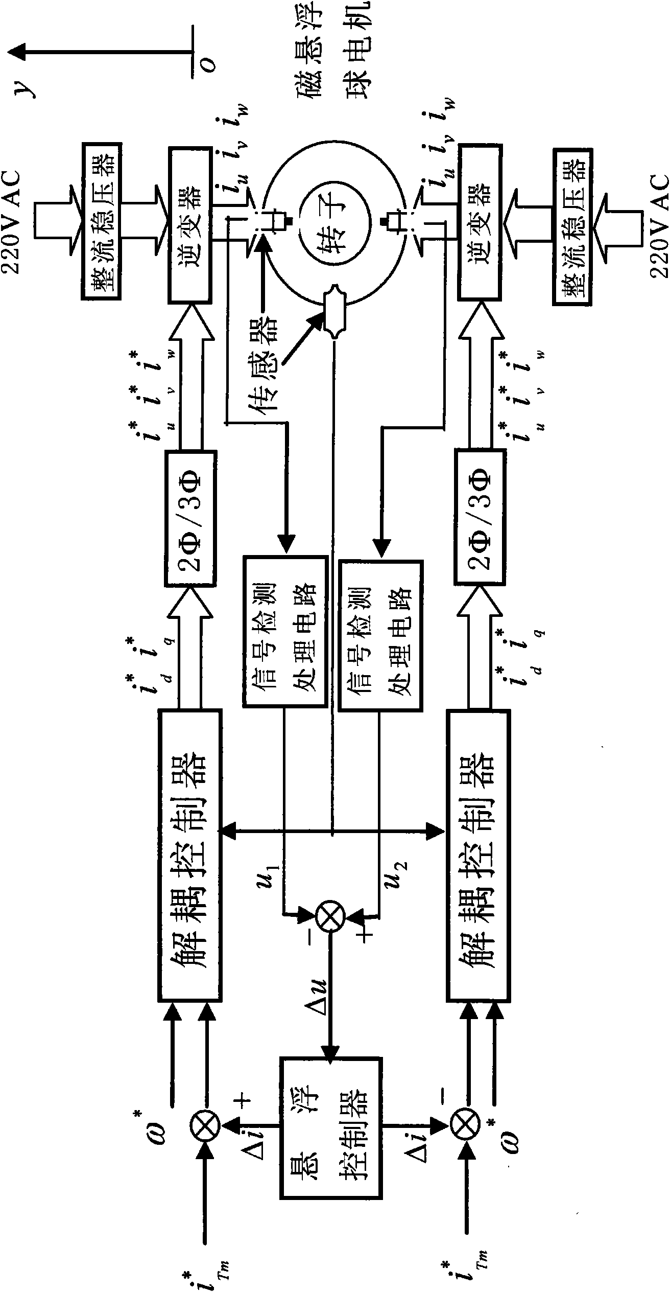
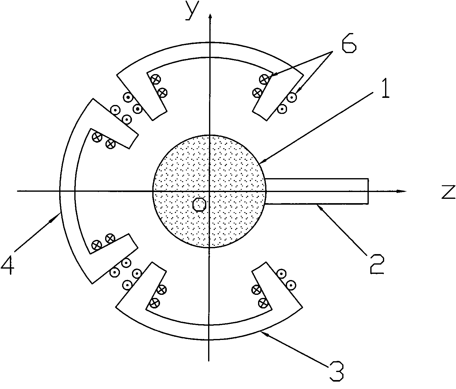
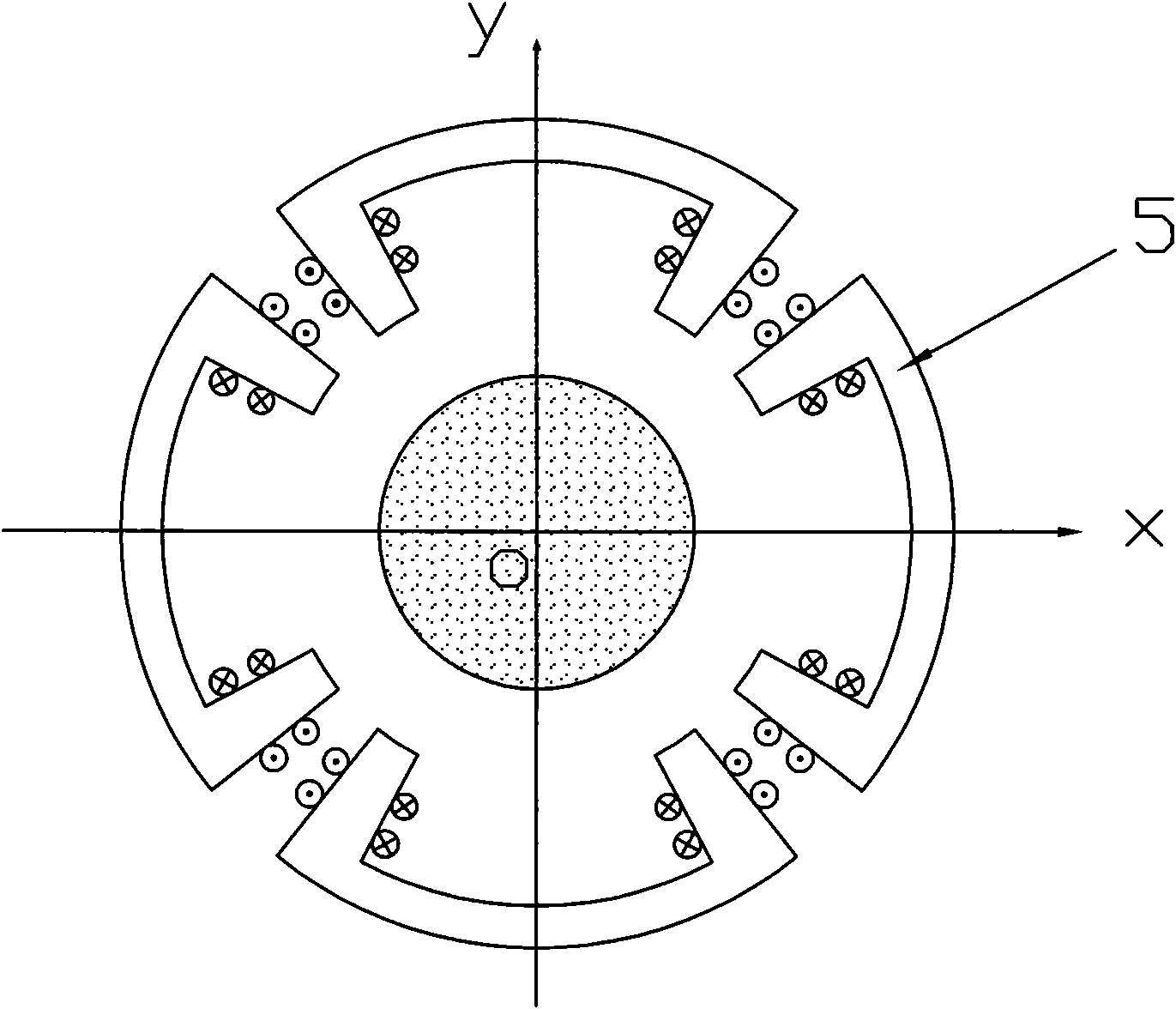
[0023] The magnetic levitation spherical motor system consists of a magnetic levitation spherical motor body and a detection and control system. The body structure of the magnetic levitation spherical motor is composed of a spherical rotor 1, an output rotating arm 2, a centripetal push (pull) force magnetic levitation spherical motor salient pole stator 3, 4, 5, and a stator energized winding 6. The salient pole stator of the magnetic levitation spherical motor is arranged orthogonally on each side of the spherical rotor 1 according to the three-dimensional coordinate system of x-y-z, with the center of the spherical rotor at the equilibrium position as the coordinate origin. Among them, one motor stator 5 is arranged symmetrically to the coordinate origin (rotor sphere center) in the...


PUM


Abstract

The invention discloses a magnetic suspension spherical electromotor system, comprising an electromotor stator, a magnetic suspension spherical electromotor which is composed of a winding, a sphericalshape rotor, an output tumbler, and a testing control system. The stator is composed of five or six split projecting pole stators; the projecting pole stators select the center of spherical shape rotor as an origin of coordinate, and distribute orthogonally on each side of the spherical shape rotor by a x-y-z 3D space coordinate system, in which two projecting pole stators are distributed along the x-direction to be symmetry to the origin of coordinate, two projecting pole stators are distributed along the y-direction to be symmetry to the origin of coordinate and one or two projecting pole stators are distributed along the z-direction, and a triphase or multiphase energization coil winding is arranged in the grooves between the projecting pole of the projecting pole stators. The structure of the invention is reasonable, simple, compact, small in volume and light in weight, and the testing control system controls the motion, suspension and rotational state of the spherical shape rotor. The spherical shape rotor has no friction and wear-out with the stators, and the invention has good dynamic property and rapid response speed.

Description

technical field [0001] The invention relates to a motor with driving capability of multiple rotational degrees of freedom, which belongs to the field of electromechanical technology and control technology. Background technique [0002] A multi-degree-of-freedom spherical motor refers to a motor that has two or three rotational degrees of freedom and can rotate around a fixed-point spatial axis. It has the characteristics of high mechanical integration, motor structural materials and high utilization of drive control system components. In a mechanical system with multiple degrees of freedom of motion, one multi-degree-of-freedom motor can replace two or more single-degree-of-freedom motors. Greatly simplify the structure of the mechanical system, reduce the size and weight, and eliminate the backlash and friction caused by gear transmission, thereby improving the accuracy and dynamic performance of the system, improving the performance-price ratio, and having advantages in co...

Claims


Application Information

Patent Timeline
Patent Type & Authority Patents(China)
IPC IPC(8): H02N15/00
Inventor 曾励张丹
Owner YANGZHOU UNIV
Features
  • R&D
  • Intellectual Property
  • Life Sciences
  • Materials
  • Tech Scout
  • Unparalleled Data Quality
  • Higher Quality Content
  • 60% Fewer Hallucinations
Learn More