Phase-controllable birefringence space light bridge

A birefringence and bridge technology, applied in the field of coherent laser communication and lidar, can solve the problems of inability to carry out phase control, difficult installation, difficult integration, etc., and achieve the effect of overcoming the complex phase control process, simple structure and stable performance.

Inactive Publication Date: 2009-10-21
SHANGHAI INST OF OPTICS & FINE MECHANICS CHINESE ACAD OF SCI
View PDF0 Cites 17 Cited by
  • Summary
  • Abstract
  • Description
  • Claims
  • Application Information

AI Technical Summary

Problems solved by technology

Although in optical fiber communication systems, people use optical fibers and waveguides to develop various optical bridge solutions, these optical bridges suitable for optical fiber communication systems cannot meet the needs of space communication, and do not belong to space optical bridges. In free space laser communication In the system, the received optical signal is not only used to detect communication information but also to extract position information for optical precision tracking. For free space laser communication terminals, the optical bridge must be free space propagation
In free-space optical bridging, prior art [1], [2] (see document 1: WalterR.leeb.Realization of 90°and 180°Hybrids for Optical Frequencies[C]. , Band 37[1983], Heft 5/6: 203-206. Literature 2: R.Garreis, C.Zeiss, "90°opticalhybrid for coherent receivers," Proc.SPIE, Vol.1522, pp.210-219, 1991.) proposed a 2×2 spatial optical bridge scheme using a polarizing beam splitter combined with a wave plate, and a non-polarizing beam splitter combined with a wave plate to achieve 90-degree and 180-degree phase shifts. Literature [2] proposed on this basis A 2×4 90-degree phase shift implementation scheme is proposed, but this scheme must make the phases of the two polarization components of the incident beam after passing through the polarizing beam splitter and the no...

Method used


Image

  • Phase-controllable birefringence space light bridge
  • Phase-controllable birefringence space light bridge
  • Phase-controllable birefringence space light bridge

Examples


Embodiment Construction

[0022] The present invention will be further described in detail below in conjunction with the accompanying drawings and examples, but the protection scope of the present invention should not be limited thereby.

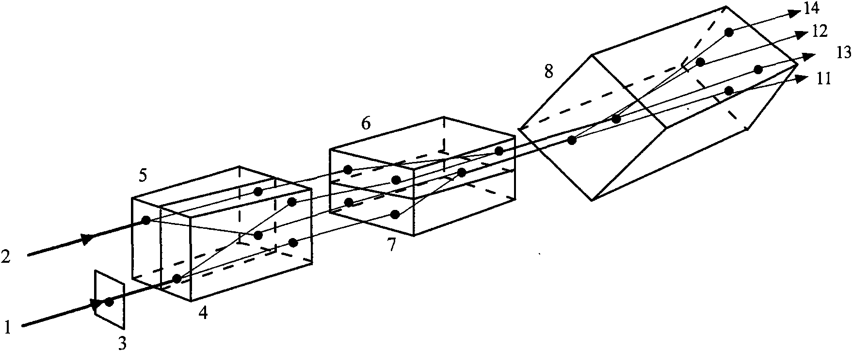
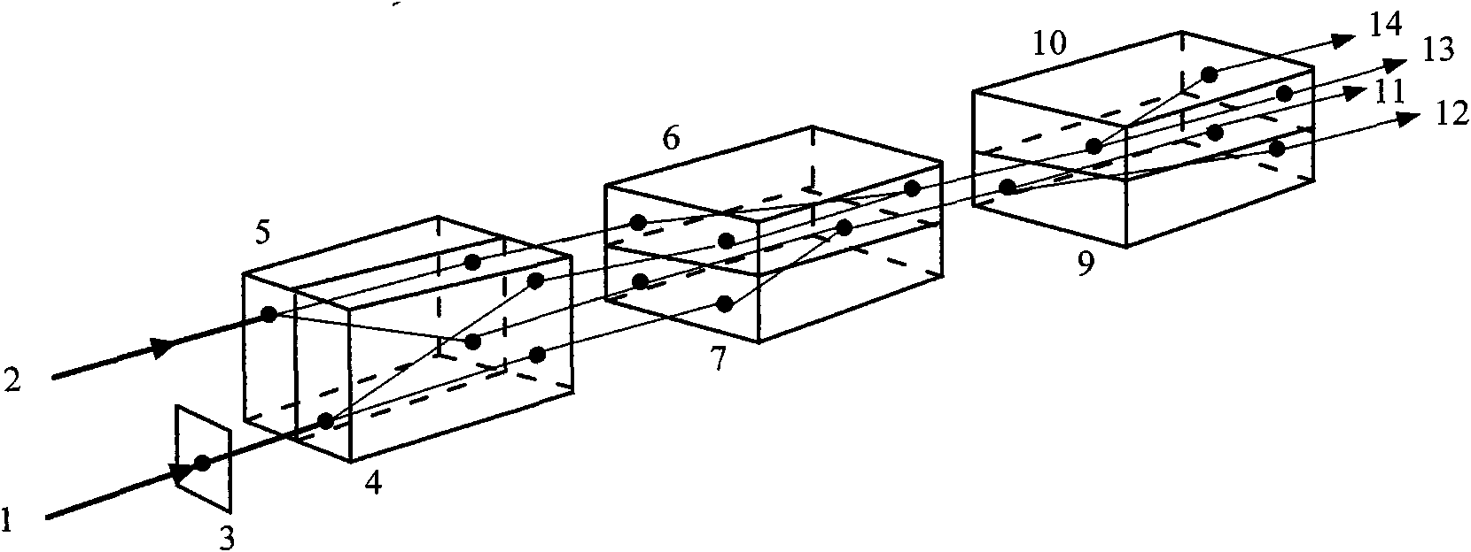
[0023] see first figure 1 ,Depend on figure 1It can be seen that Embodiment 1 of the phase controllable birefringent optical bridge of the present invention consists of a quarter-wave plate 3, a first birefringent optical plate 4, a second birefringent optical plate 5, a third birefringent optical plate 6, The 4th birefringent optical flat plate 7 and an analyzer birefringent optical flat plate 8 constitute, and the position relation of above-mentioned each component is: the optical axis orientation of described first birefringent optical flat plate 4 and the second birefringent optical flat plate 5 are opposite and Stacked together to form a first stack, the optical axis orientation of the third birefringent optical flat plate 6 and the fourth birefringent optical ...


PUM


Abstract

The invention relates to a phase-controllable birefringence space light bridge, which uses a combined birefringence optical flat to achieve light splitting synthesis of two input light beams, wherein a quarter-wave plate performs phase-shift control and is used for space compounding of a laser communication signal light beam and a local oscillation laser beam in a coherent optical communication receiver and outputting four paths of synthesized light beams with a required phase-shift relation so as to achieve 2*4 space light bridging. The quarter-wave plate makes two perpendicular polarized components generate 90-degree phase shift, and the phase difference between the two components can be changed by rotating the optical axis direction so as to compensate phase errors generated by errors of processing, assembling, calibration and the like, thus the phase-controllable birefringence space light bridge has the advantages of simple structure, stable performance and controllable phase. The phase-controllable birefringence space light bridge is applicable in the field of free space laser coherent communication and laser radar.

Description

technical field [0001] The invention relates to coherent laser communication and laser radar, in particular to a phase controllable birefringence space light bridge. The combined birefringent optical plate is used to spatially couple the two input beams and divide them into four synthetic beams for output, realizing a 2×4 spatial optical bridge. The machine is used for spatial composite laser signal beam and local oscillator laser beam, and generates a 90-degree 2×4 spatial optical bridge that can be phase-controlled as required. Background technique [0002] Space-borne laser communication terminals that realize large capacity, high bit rate, small size, light weight and low power consumption are the needs of free space laser communication. Since the receiver sensitivity of coherent optical communication is more than an order of magnitude higher than that of incoherent optical communication, and a variety of modulation methods can be adopted to increase receiver selectivit...

Claims


Application Information

Patent Timeline
IPC IPC(8): G02B26/06G02B27/28G02B5/30H04B10/10H04B10/11
Inventor 万玲玉刘立人孙建锋周煜职亚楠许楠闫爱民
Owner SHANGHAI INST OF OPTICS & FINE MECHANICS CHINESE ACAD OF SCI
Why Eureka
Try Eureka