Optical time division multiplexer and manufacturing method

A multiplexer and time-division technology, applied in the information field, can solve problems such as optical time-division multiplexers that have not been reported, and achieve high commercial value and low production cost.

Inactive Publication Date: 2013-04-10
BEIJING JIAOTONG UNIV
View PDF0 Cites 0 Cited by
  • Summary
  • Abstract
  • Description
  • Claims
  • Application Information

AI Technical Summary

Problems solved by technology

[0007] In order to overcome the deficiencies of the prior art structure and aim at the problems existing in the above-mentioned structured light time division multiplexer, the present invention innovatively adopts a novel Whiteman type interferometer structured light time division multiplexer combined with an optical fiber and a coated bulk optical device to solve The stability problem of the optical time division multiplexer is solved, and the optical time division multiplexer of this structure has not been reported at home and abroad.

Method used


Image

  • Optical time division multiplexer and manufacturing method
  • Optical time division multiplexer and manufacturing method
  • Optical time division multiplexer and manufacturing method

Examples


Embodiment 1

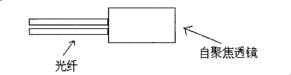
[0063] Embodiment 1: as Figure 4 As shown, the first-stage Whiteman interferometric optical time division multiplexer, when the frequency before multiplexing is 2.5GHz, the frequency after multiplexing is 5GHz, and the self-focusing lens adopts a quarter-pitch rod lens with the function of collimating light . The refractive index distribution of the self-focusing lens is:

[0064] n=n 0 [1-1 / 2Ar 2 ] (1)

[0065] In the formula, n 0 is the refractive index of the glass on the axis, A is the distribution constant, and r is the radius.

[0066] Under the paraxial meridional approximation, the ray equation simplifies to

[0067] dx 2 dz 2 = - Ax - - - ( 2 )

[0068] Among them, x represents the vertical distance from the light to the axis, and z represents the ho...

Embodiment 2

[0104] Embodiment 2: The following structures all belong to the scope of the patent requirements:

[0105] (1) The end face of the optical fiber is fired into a lens shape by various heating methods to turn the light into parallel light; a pair of such devices are placed between a pair of splitting films or splitting sheets of various splitting ratios to form a fiber optic lens type Whiteman interferometer optical division multiplexer, such as Figure 15 shown. Figure 15 Among them, H1...H4 represent 4 sets of components cascaded. 2 sets, 4 sets, ..., 2n sets (n=1, 2, ∞) all belong to the scope of this patent.

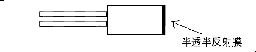
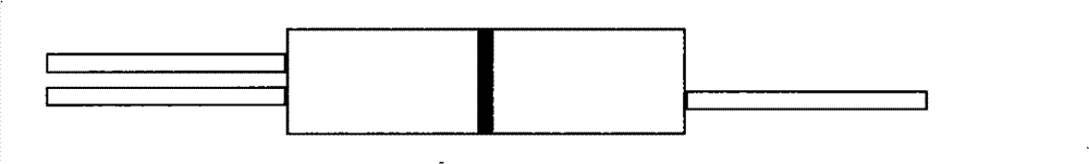
[0106] (2) The self-focusing lens with pigtails is coated with a spectroscopic film, and the optical fiber self-focusing rod-lens type Whiteman optical fiber interferometer optical division multiplexer is formed, such as Figure 16 shown.

[0107] superior Figure 16 The middle is the optical division multiplexer of the 4-stage Whiteman fiber interferometer. Lev...

Embodiment 3

[0110] The self-focusing lens adopts a quarter-pitch rod lens with the function of collimating light. The refractive index distribution of the self-focusing lens is:

[0111] n=n 0 [1-1 / 2Ar 2 ] (1)

[0112] In the formula, n 0 is the refractive index of the glass on the axis, A is the distribution constant, and r is the radius.

[0113] Under the paraxial meridional approximation, the ray equation simplifies to

[0114] dx 2 dz 2 = - Ax - - - ( 2 )

[0115] Among them, x represents the vertical distance from the light to the axis, and z represents the horizontal position starting from the incident end.

[0116] Integrate (2) and bring into the boundary conditions to get:

[0117] x ...


PUM

PropertyMeasurementUnit
lengthaaaaaaaaaa
refractive indexaaaaaaaaaa

Abstract

The invention relates to an optical time division multiplexer, which consists of a multi-level Wightman interferometer. Each level of Wightman interferometer consists of a fiber pigtail, a self-focusing lens and a light splitting film; the fiber pigtail is coupled with the self-focusing lens to form a fiber collimating lens; the end face of the fiber collimating lens is plated with the light splitting film; a pair of the fiber collimating lenses plated with the light splitting film form a fiber light-splitting device; two fiber light-splitting devices form a level of the Wightman interferometer; and each level of the Wightman interferometer can double the optical signal rate by properly adjusting the length difference of interference arms, and n levels of the Wightman interferometer can improve the optical signal rate by n times, wherein n is 1, 2, 3, 4, and the like. The optical time division multiplexer has the advantages that: based on the defect improvement of the conventional timedivision multiplexer, compared with the time division multiplexers of foreign companies, the optical time division multiplexer is superior to the foreign products in the aspects of loss, wavelength flatness, polarization sensitivity, temperature stability and the like, and has low manufacturing cost and large commercial value.

Description

technical field [0001] The invention relates to an optical time division multiplexer and a manufacturing method, belonging to the field of information technology. Background technique [0002] A substantial increase in communication capacity is an inevitable trend in the development of an information society, and Optical Time Division Multiplexing (OTDM) and Dense Wavelength Division Multiplexing (DWDM) are two important and effective ways to increase optical fiber communication capacity. OTDM technology and DWDM technology are two different technical routes to realize future high-speed, large-capacity optical fiber communication system, and a large-capacity optical fiber communication system can be constructed by using either technology alone. The combination of OTDM technology and DWDM technology can make full use of the advantages of these two technologies and discard their shortcomings, and jointly build the future of high-speed and large-capacity optical fiber communica...

Claims


Application Information

Patent Timeline
Patent Type & Authority Patents(China)
IPC IPC(8): H04J14/08G02F1/35
Inventor 李唐军王目光简水生钟康平
Owner BEIJING JIAOTONG UNIV
Why Eureka
Try Eureka