
High frequency filter with closed circuit coupling

A high-frequency filter and band-stop filter technology, which is applied to waveguide devices, circuits, electrical components, etc., can solve the problem of limited quantity and achieve the effect of reducing the overall structure height

Active Publication Date: 2009-10-21
TELEFON AB LM ERICSSON (PUBL)
View PDF9 Cites 8 Cited by
  • Summary
  • Abstract
  • Description
  • Claims
  • Application Information

AI Technical Summary

Problems solved by technology

[0012] Due to the limited number of resonator pairs suitable for cross-coupling, only a limited number of blocking electrodes can be produced

Method used


Image

  • High frequency filter with closed circuit coupling
  • High frequency filter with closed circuit coupling
  • High frequency filter with closed circuit coupling

Examples


Embodiment Construction

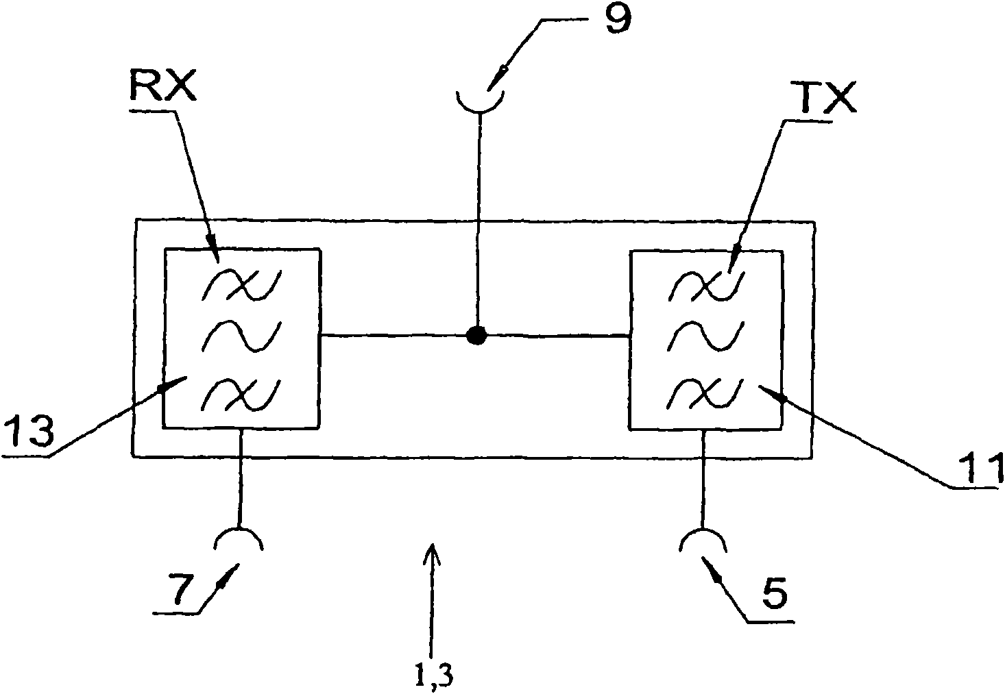
[0038] exist figure 1 A high-frequency filter in the form of a duplex split filter 3 is shown schematically in , wherein the high-frequency filter 1 comprises three terminals 5, 7, 9, namely the terminals TX, RX and a terminal for the antenna port AP , so that the transmitted signal can go from the transmitting terminal 5 to the antenna port AP (the port of the common antenna) through the first signal path, and the signal received by the antenna can be led to the receiving terminal 7 through the antenna port AP (terminal 9).

[0039] For this purpose, the duplex splitter filter 3 comprises corresponding bandpass filters 11 and 13 in each of the two signal paths, which bandpass filters have the necessary selection (that is to say suppress attenuation), so that it is not possible to A signal arrives in the receiving branch. On the other hand, the passband range should be attenuated as little as possible for the useful signal.

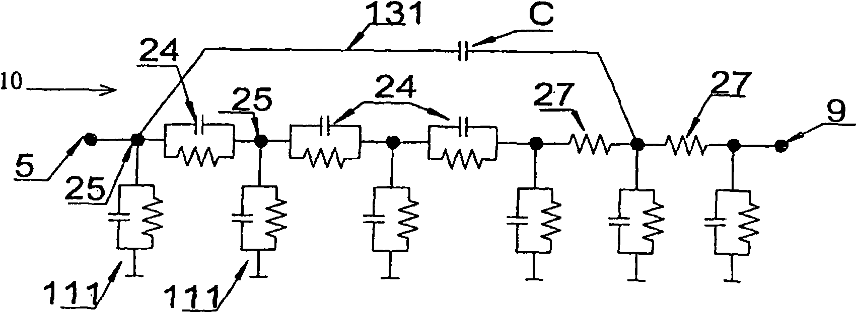
[0040] for this in figure 2 In the figure, for ...


PUM


Abstract

The invention relates to an improved high frequency filter having the following features: the high frequency filter has a transmission behavior with a coupling impedance resonance with at least one null point at a frequency (fs), wherein the null point at the frequency (fs) can be set by specifying and / or preselecting a defined capacitive (12 / ') and inductive (12 / '') coupling between two coaxial resonators (15) directly following one another on a signal path (10).

Description

technical field [0001] The invention relates to a high-frequency filter with band-stop filter loop coupling according to the preamble of claim 1 . Background technique [0002] High frequency filters are used in a wide range of fields. [0003] For example in digital mobile radio technology, the communication between the mobile subscriber and the base station takes place via a transmit-receive antenna arranged in the base station. It is desirable here to use only one common antenna for transmitting and receiving signals. [0004] In this case, different frequency ranges are used for the transmitted signal and the received signal. The antennas used must be suitable for transmitting and receiving in both frequency ranges. In order to separate transmitted and received signals, appropriate frequency filtering is required, which ensures that on the one hand the transmitted signal is forwarded by the transmitter only to the antenna (and not in the direction of the receiver), an...

Claims


Application Information

Patent Timeline
Patent Type & Authority Applications(China)
IPC IPC(8): H01P1/205H01P1/213
CPCH01P1/2053H01P1/2136H01P1/205H01P1/213
Inventor W·魏岑博格
Owner TELEFON AB LM ERICSSON (PUBL)
Learn More