
Compaction forming construction method of concrete poured on the base of structure and device thereof

A technology of pouring concrete and construction methods, which is applied in basic structure engineering, basic structure repair, construction, etc. It can solve the problems of prolonging the construction period, affecting the appearance, increasing the newly poured part, etc., shortening the construction period and simplifying the design scheme , a clear effect of force

Inactive Publication Date: 2009-10-28
JIANGSU JIANHUA CONSTR
View PDF0 Cites 15 Cited by
  • Summary
  • Abstract
  • Description
  • Claims
  • Application Information

AI Technical Summary

Problems solved by technology

[0003] In [Code for Reinforcement of Concrete Structures] GB50367-2006, the "increased section reinforcement method" is listed, that is, the section expansion method of bending and compression members. Taking the enlarged section of the beam bottom as an example, the specification does not point out that it is different from the existing beam section. How to pour the newly poured part of the same width, for this kind of cross-section, in order to facilitate pouring, the width of the newly poured part must be increased. If the excess part is not removed after the concrete solidifies, it will affect the appearance; or the excess part must be damaged. ; Or use static cutting, which will inevitably increase cutting costs
[0004] Other reinforcement methods listed in [Specification] generally need to rely on the existing member section. If the section condition is not satisfied, there is no explanation to take other measures. Generally, the designer can only dismantle the existing member and redo it.
The "adding fulcrum reinforcement method" also involves the problem of how to pour the newly poured concrete fulcrum and the upper existing member without opening the upper structure, and adding a fulcrum will cause certain obstacles to the use function
[0005] [Specifications] When the upper structure cannot be entered into the construction, that is, the upper concrete structure cannot be opened or the upper structure is not removed, and the existing beam needs to expand the section on three sides (both sides and the bottom) or add concrete beams under the slab to meet the actual requirements. , did not make any suggestions. Therefore, in the renovation or reinforcement of concrete structures due to reinforcement or improvement of bearing capacity, designers often need to pour new concrete at the bottom or side of the existing structure. Generally, they can only be demolished and poured first. The original structural components blocked above the surface, and the new and old structures are recast together
In this way, firstly, the investment cost is increased, secondly, the construction period is prolonged, and thirdly, if the upper part of the structure is owned by others, because it affects the normal use of the structure by others, it also involves coordination work issues
[0006] In addition, when the upper structure cannot be dismantled, due to the limitations of the existing concrete construction methods, designers can only design new load-bearing components below a certain distance from the existing structure, and use bricklaying or filling between the old and new structures Other hard blocks for force transmission; a new steel beam will be built at the bottom surface of the existing structure, and steel wedges will be inserted between the steel beam and the upper concrete structure to transmit force
The use of these relatively reluctant reinforcement schemes cannot make the old and new structures form an integral structure, which is not conducive to the overall stress of the structure, and is also very uneconomical.

Method used


Image

  • Compaction forming construction method of concrete poured on the base of structure and device thereof
  • Compaction forming construction method of concrete poured on the base of structure and device thereof
  • Compaction forming construction method of concrete poured on the base of structure and device thereof

Examples


example 1

[0083] Example 1: The extruded slab is 1.0m long and 0.3m high, and the width of the cast beam is 0.5m. The extruded slab on each side is pushed horizontally to the full cylinder a=0.25m, the concrete slump is 16cm, and the twin-screw M12 is selected. Q235 steel, double thread z=2, pitch p=1.75mm, middle diameter d 2 =10.863mm, minor diameter d 1 =10.106mm, standard coarse tooth, friction coefficient f=0.15, force F acting on the wrench max =100N,, the effective radius of the moment arm l=500mm.

example 2

[0084] Example 2: φ150mm circular cross-section cylinder, pushed up to compact 1m, single screw M16, Q345 steel, middle diameter d 2 =14.701mm, minor diameter d 1 =13.835mm, the force F acting on the wrench max =144N, the effective radius of the arm of force l=500mm, and other parameters are the same as Example 1.

[0085] Table calculation, Table 2 shows the design and calculation process of the reinforcing screw for the piston-type compaction push-casting concrete forming and the internal pressure stress of the newly poured concrete.

[0086] Table 2: M12, M16 reinforced screw design and internal compressive stress of concrete

[0087]

[0088] (2) Construction part

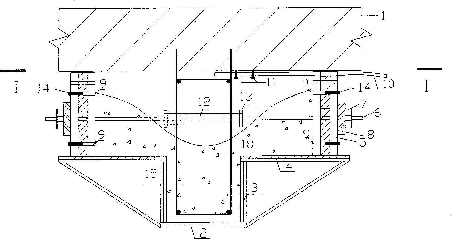
[0089] (1) Method 1, a concrete beam is poured under a closed original concrete slab, and the figure 1 , eject the outer edge of the precast beam side form (the sum of the width of the beam and the thickness of the two extruded slabs) at the bottom of the original slab (1), and draw the scale line of the...


PUM

PropertyMeasurementUnit
Middle diameteraaaaaaaaaa
Trailaaaaaaaaaa

Abstract

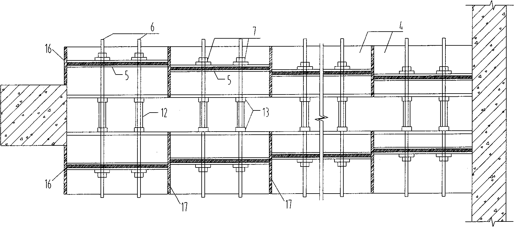
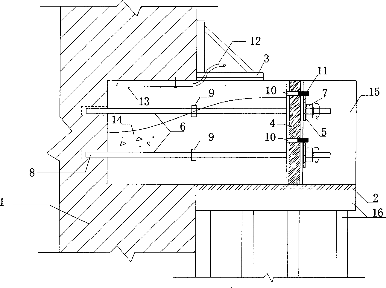
A compaction forming construction method of the concrete poured on the base of the structure and a device thereof belong to the field of civil engineering. The invention relates to the compaction forming construction method for directly pouring concrete on the lower part of prior structure and the device thereof. The method and the device of the invention are not restricted by the obstruction of the upper structure. The concrete can be extruded and pushed to a formwork to be poured and extruded to compact for forming in a horizontal direction of the side surface or a vertical direction from bottom to up. The bearing capacity of the prior structure is improved or the prior structure is reinforced. The extruding device is installed to the bottom or side surface of the existing structure. The concrete to be poured is filled in a cylinder body (4). After an extruding plate (5) is pushed for squeezing the concrete (15) forwards in the horizontal direction or upwards in the vertical direction through a force applying nut (11) or a jack, the stable pushing force is kept for extruding the new concrete to compact in one time for completing the pouring task. The device of the invention is composed of a cylinder body (4) with circular or square cross section, a piston type pushing extraction plate (5), a force transmitting screw bolt (6), the force applying nut (11), etc.

Description

Technical field [0001] The invention relates to a construction method and device for compacting and forming of concrete structures such as buildings, bridges, tunnels, dams, liquid storage tanks, silos, nuclear reactor shells, etc., which need to be poured on the bottom or side of existing structures due to renovation or reinforcement. field of civil engineering. Background technique [0002] Because concrete has a certain fluidity (slump), the traditional concrete pouring method is to first set up the formwork according to the design shape of the component, and then pour the concrete directly into the formwork from top to bottom, vibrate and compact, and form a structural member after solidification . [0003] In [Code for Reinforcement of Concrete Structures] GB50367-2006, the "increased section reinforcement method" is listed, that is, the section expansion method of bending and compression members. Taking the enlarged section of the beam bottom as an example, the specif...

Claims


Application Information

Patent Timeline
IPC IPC(8): E04G23/02E02D37/00E01D22/00
Inventor 李树林李延和
Owner JIANGSU JIANHUA CONSTR
Learn More