Illuminating device and light engine thereof

一种照明装置、光源的技术,应用在照明装置、照明装置的冷却/加热装置、照明和加热设备等方向,能够解决光衰照明装置、缩小与轻化照明装置、照明装置发光亮度、使用寿命折扣等问题,达到低结点温度、高效率照明效果的效果

Inactive Publication Date: 2009-10-28
CHAMP TECH OPTICAL FOSHAN +1
View PDF0 Cites 11 Cited by
  • Summary
  • Abstract
  • Description
  • Claims
  • Application Information

AI Technical Summary

Problems solved by technology

[0004] The application of high-power and high-brightness LEDs in the new light source of lighting must cooperate with a high-efficiency heat dissipation mechanism to minimize the junction temperature of the LEDs in order to take advantage of the above-mentioned advantages. Otherwise, the luminous brightness and service life of the lighting device will be greatly reduced, affecting all And will make the energy-saving effect of the lighting device not obvious, and directly impact the reliability of the lighting device, cause serious light decay and even make the lighting device invalid
[0005] In order for the semiconductor lighting device to continuously introduce lower temperature airflow from the outside, it is necessary to establish a low-resistance cooling airflow channel in the lighting device; under the condition of not using a fan, lighting applications with low output power can use low airflow driving force In addition to the natural circulation heat dissipation, it can also be achieved through a large heat dissipation area; however, in high-power and high-brightness lighting applications, often due to space or weight constraints and cost considerations, the use of fan cooling is very important for light and small lighting devices , reduce costs and improve heat dissipation efficiency have significant benefits; although existing semiconductor lighting devices have seen products using fans, but because the cooling airflow is only guided on the side of the fins, the benefits of reducing and lightening the lighting device cannot be fully utilized, and The cooling effect of the forced airflow cannot be fully displayed, which affects the stability and service life of the lighting device

Method used


Image

  • Illuminating device and light engine thereof
  • Illuminating device and light engine thereof
  • Illuminating device and light engine thereof

Examples


Embodiment Construction

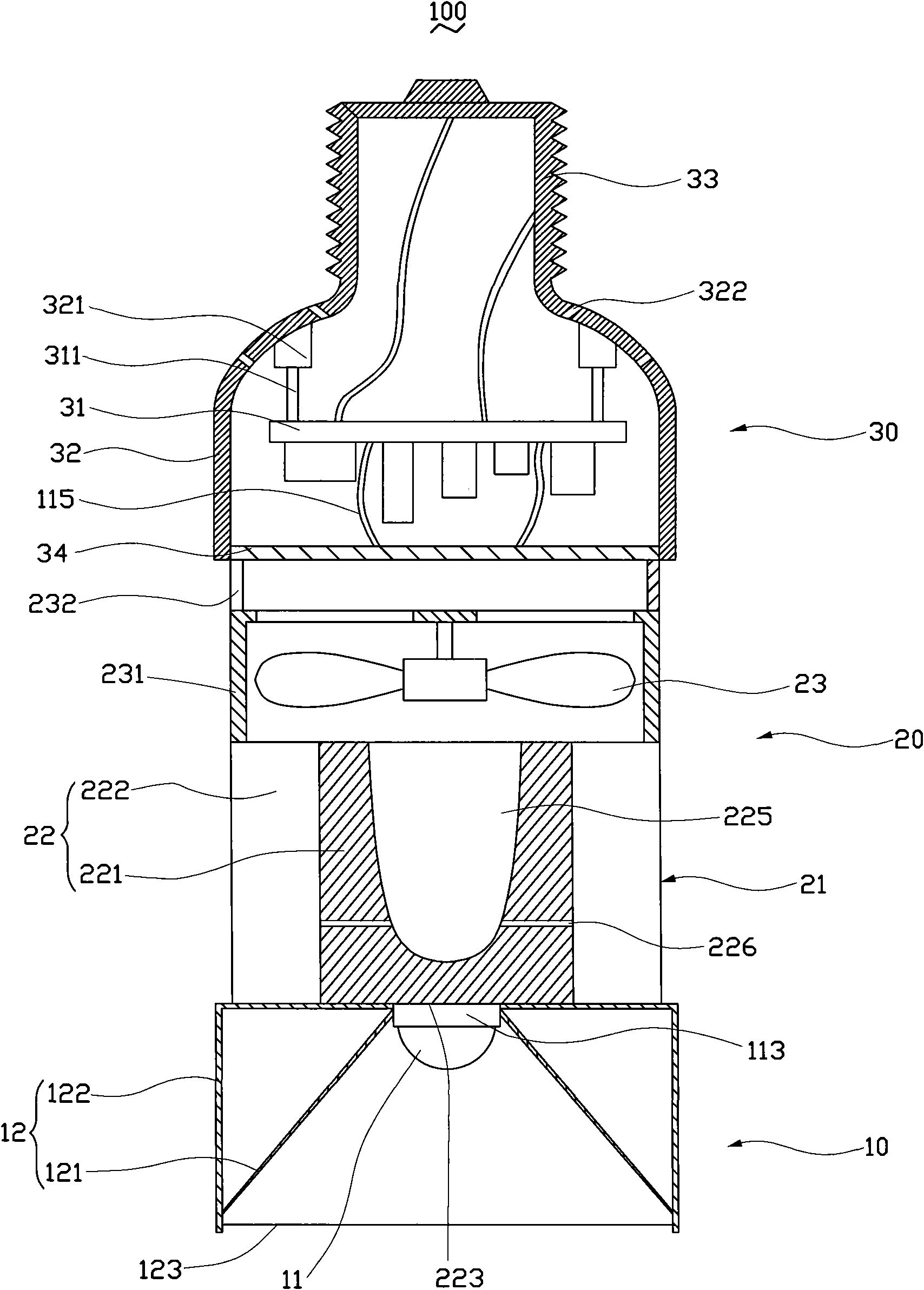
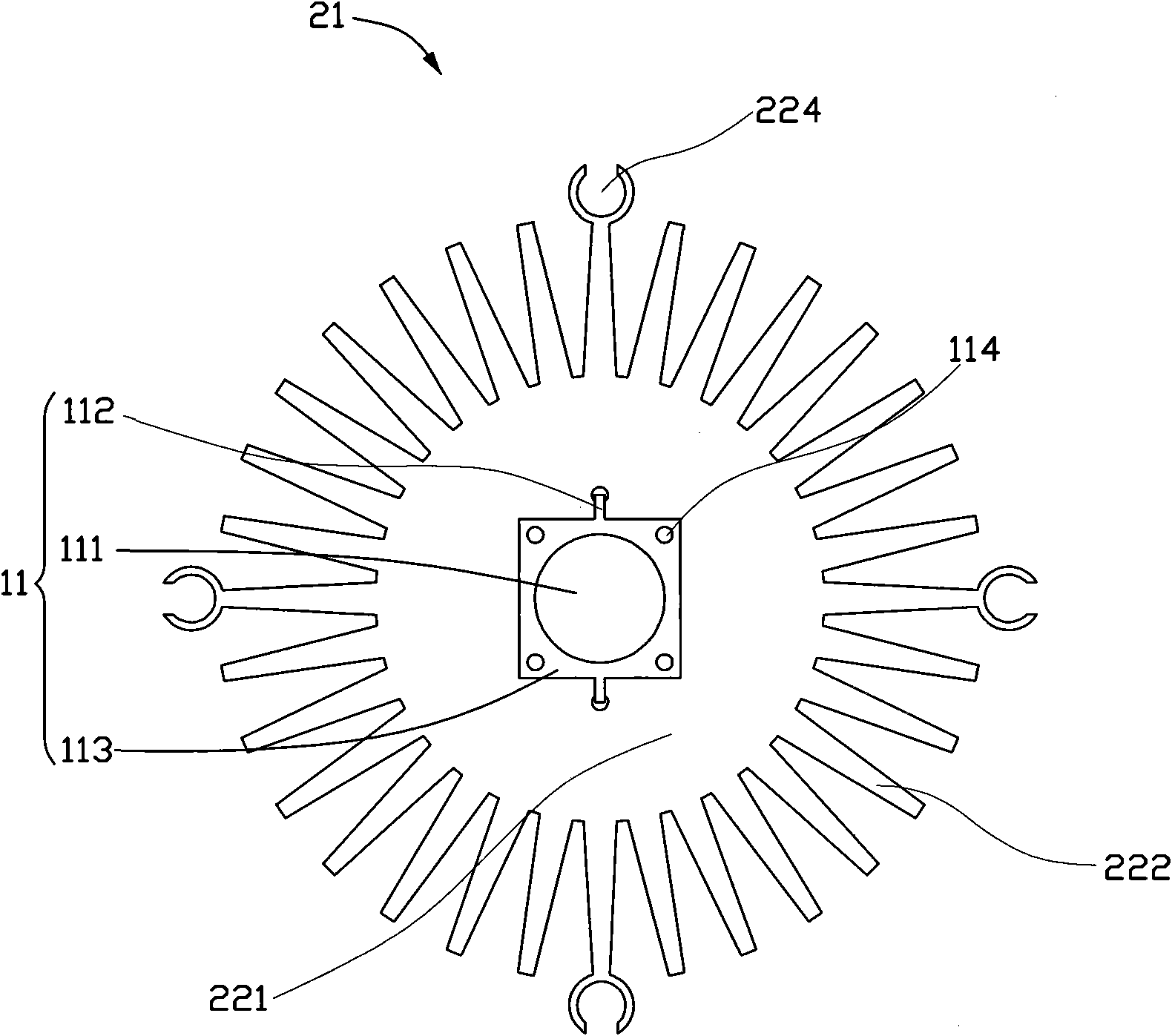
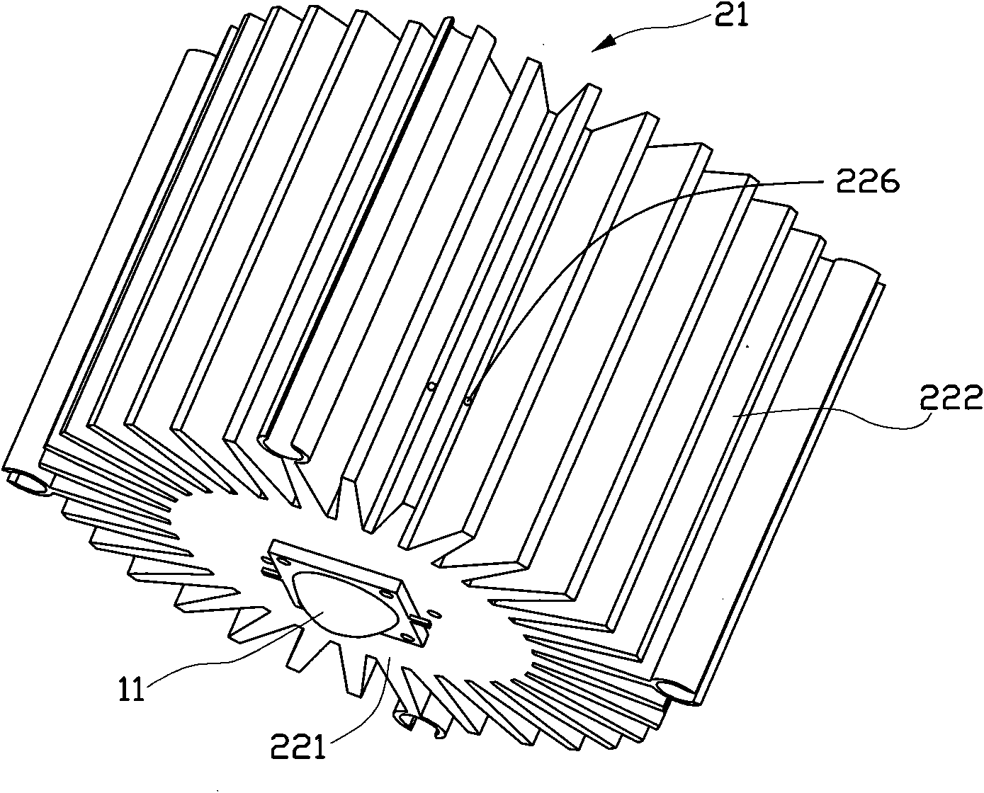
[0020] figure 1 It is a schematic cross-sectional view of the assembly of the first embodiment of the lighting device and its light engine of the present invention, figure 2 yes figure 1 Bottom view of the light engine shown, image 3 yes figure 1 The perspective view of the light engine shown; the lighting device 100 mainly includes an optical chamber 10 , a heat dissipation chamber 20 and an electrical chamber 30 . in:

[0021] The optical chamber 10 includes a light source 11 and a light exit channel 12, which are arranged in front of the heat dissipation chamber 20. The light source 11 includes a transparent encapsulation illuminant 111 (Emitter) composed of at least one semiconductor light-emitting chip, a number of electrodes 112, and an emitter located on the emitter. 111 bottom of at least one integral molding of heat dissipation substrate 113 ( figure 2 As shown), the electric wire 115 can connect the driving power provided in the electric chamber 30 and the el...


PUM


Abstract

The invention relates to an illuminating device which comprises an optical chamber, an electric chamber, and a radiating chamber arranged between the optical chamber and the electric chamber, wherein the optical chamber comprises at least one light source and a light emission channel; the radiating chamber comprises a radiator and a fan, the radiator is provided with a solid body and a plurality of fins radially distributed on the circumference of the solid body, one end of the solid body, which is close to the optical chamber, thermally contacts with the light source, one end of the solid body, which is close to the electric chamber, inwards concaves to form a cavity body, the periphery of the cavity, which is close to one end of the light source and corresponds to each fin, is provided with a plurality of air holes to form an airflow channel guiding cooling flow to flow through the cavity body, the fan is arranged between the radiator and the electric chamber, one part of airflow guided by the fan flows among the fins of the radiator, and the other part flows through the airflow channel formed by the cavity body and the air holes.

Description

technical field [0001] The invention relates to a lighting device, in particular to a semiconductor lighting device with high heat dissipation efficiency and a light engine thereof. Background technique [0002] People's long-term over-reliance on fossil fuels not only causes energy shortages and high oil prices, which affects economic development, but also increases the concentration of global carbon dioxide and harmful gas emissions, leading to climate anomalies caused by global warming, ecological environment damage, and The harm to human existence is becoming more and more obvious. In order to sustainably manage the earth's ecological environment on which human beings depend, it is necessary to solve the energy crisis and environmental pollution problems at the same time. The development of new energy and renewable energy is the most important strategy to promote energy conservation and efficient use of energy , while traditional lighting consumes a considerable amount o...

Claims


Application Information

Patent Timeline
Patent Type & Authority Applications(China)
IPC IPC(8): F21V29/00F21V29/02H01L23/367H01L23/467F21Y101/02
CPCF21V29/02H01L2924/0002F21Y2101/02F21K9/137F21V29/2231F21K9/00F21V29/2293F21V29/027F21V29/2262F21V29/004F21V29/67F21V29/677F21V29/75F21V29/773F21V29/83F21K9/233F21Y2115/10H01L2924/00
Inventor 刘泰健
Owner CHAMP TECH OPTICAL FOSHAN
Why Eureka
Try Eureka