Method and device for preventing eyeglass collision

A technology of lens and moving direction, applied in the direction of exposure device of photoengraving process, exposure equipment of microlithography, etc., can solve the problems of collision and damage of movable lens, achieve simple and reliable structure, prevent collision, and reduce maintenance and repair cost. Effect

Active Publication Date: 2009-10-28
SHANGHAI MICRO ELECTRONICS EQUIP (GRP) CO LTD
View PDF0 Cites 0 Cited by
  • Summary
  • Abstract
  • Description
  • Claims
  • Application Information

AI Technical Summary

Problems solved by technology

However, there is an overlapping area between the strokes of the movable lens, so the movable lens will collide and cause damage

Method used


Image

  • Method and device for preventing eyeglass collision
  • Method and device for preventing eyeglass collision
  • Method and device for preventing eyeglass collision

Examples


Embodiment Construction

[0024] Embodiments of the present invention are described below through specific examples, and those skilled in the art can easily understand other advantages and effects of the present invention from the content disclosed in this specification. The present invention can also be implemented or applied through other different specific examples, and various modifications and changes can be made to the details in this specification based on different viewpoints and applications without departing from the spirit of the present invention.

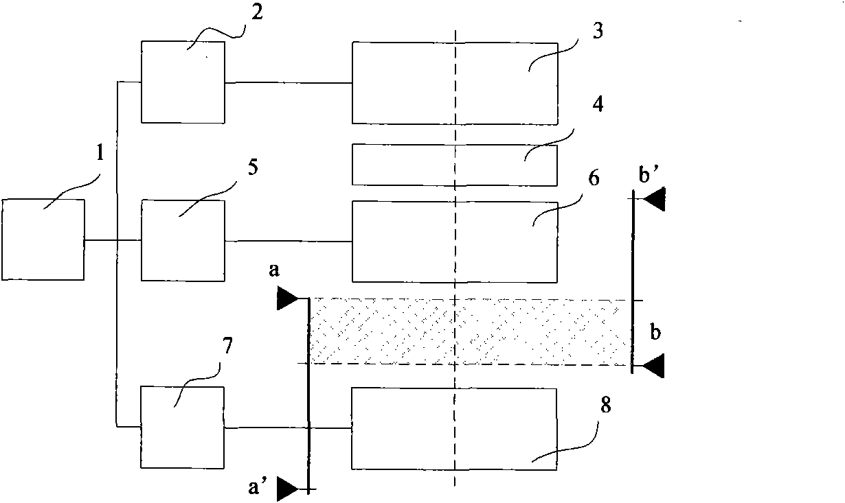
[0025] The method and device for preventing lens collision described in the present invention can be applied in the lighting system of lithography equipment. The lighting system includes at least two movable lenses arranged adjacently, and there is a overlapping areas. A possible situation such as figure 1 As shown, the lens 6 and the lens 8 are movable lenses arranged adjacently, wherein the stroke range of the lens 6 is the distance between b...


PUM


Abstract

The invention provides a method and device for preventing eyeglass collision, which reasonably arranges the moving sequence of the eyeglass through judging the moving direction of the eyeglass, thereby achieving the effect of preventing eyeglass collision. Moreover, the device for preventing eyeglass collision can also be additionally provided with a detecting module so as to guarantee, has a simple and reliable structure, does not need strict limitation on the mechanical mounting conditions, and dose not make erroneous judgments, does not conduct faulty operations which causes movable eyeglasses to be destroyed during the power-off assembling and adjusting process and simultaneously can reduce the maintaining and repairing costs.

Description

technical field [0001] The invention relates to a device for preventing lens collision, in particular to a device for preventing lens collision in photolithography technology. Background technique [0002] The rapid development of modern semiconductor technology, in which optical lithography technology plays an important role. In the application of optical lithography technology in semiconductors, the designed circuit is made into a light-transmitting mask with a specific shape. Using the principle of exposure, the light source is projected onto the silicon wafer through the mask, and a specific pattern can be exposed and displayed. [0003] The lithography equipment has been able to form smaller and smaller patterns on the wafer, but in the lithography process, in order to meet the required process conditions, it is necessary to set the illumination mode. However, there is travel interference between the coaxial optical lenses used to set the lighting mode, that is, the mo...

Claims


Application Information

Patent Timeline
Patent Type & Authority Applications(China)
IPC IPC(8): G03F7/20
Inventor 江潮徐文罗闻
Owner SHANGHAI MICRO ELECTRONICS EQUIP (GRP) CO LTD
Why Eureka
Try Eureka