
Method for producing STI lining oxide layer

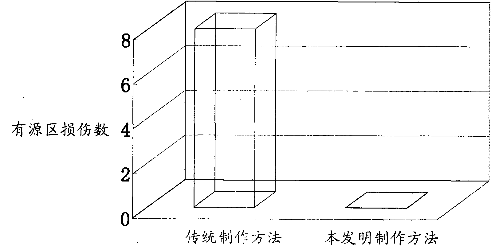
A technology of lining oxide layer and oxidizing gas, which is applied in semiconductor/solid-state device manufacturing, electrical components, circuits, etc., and can solve problems such as active area damage

Active Publication Date: 2009-10-28
SEMICON MFG INT (SHANGHAI) CORP
View PDF0 Cites 3 Cited by
  • Summary
  • Abstract
  • Description
  • Claims
  • Application Information

AI Technical Summary

Problems solved by technology

[0003] The present invention provides a method for making the lining oxide layer of STI, so as to avoid the formation of silicon nitride in the active region on the substrate under the condition of nitrogen annealing in the traditional manufacturing of the lining oxide layer of STI, and solve the problems caused by the subsequent silicon nitride removal process. source damage problem

Method used


Image

  • Method for producing STI lining oxide layer
  • Method for producing STI lining oxide layer
  • Method for producing STI lining oxide layer

Examples


Embodiment Construction

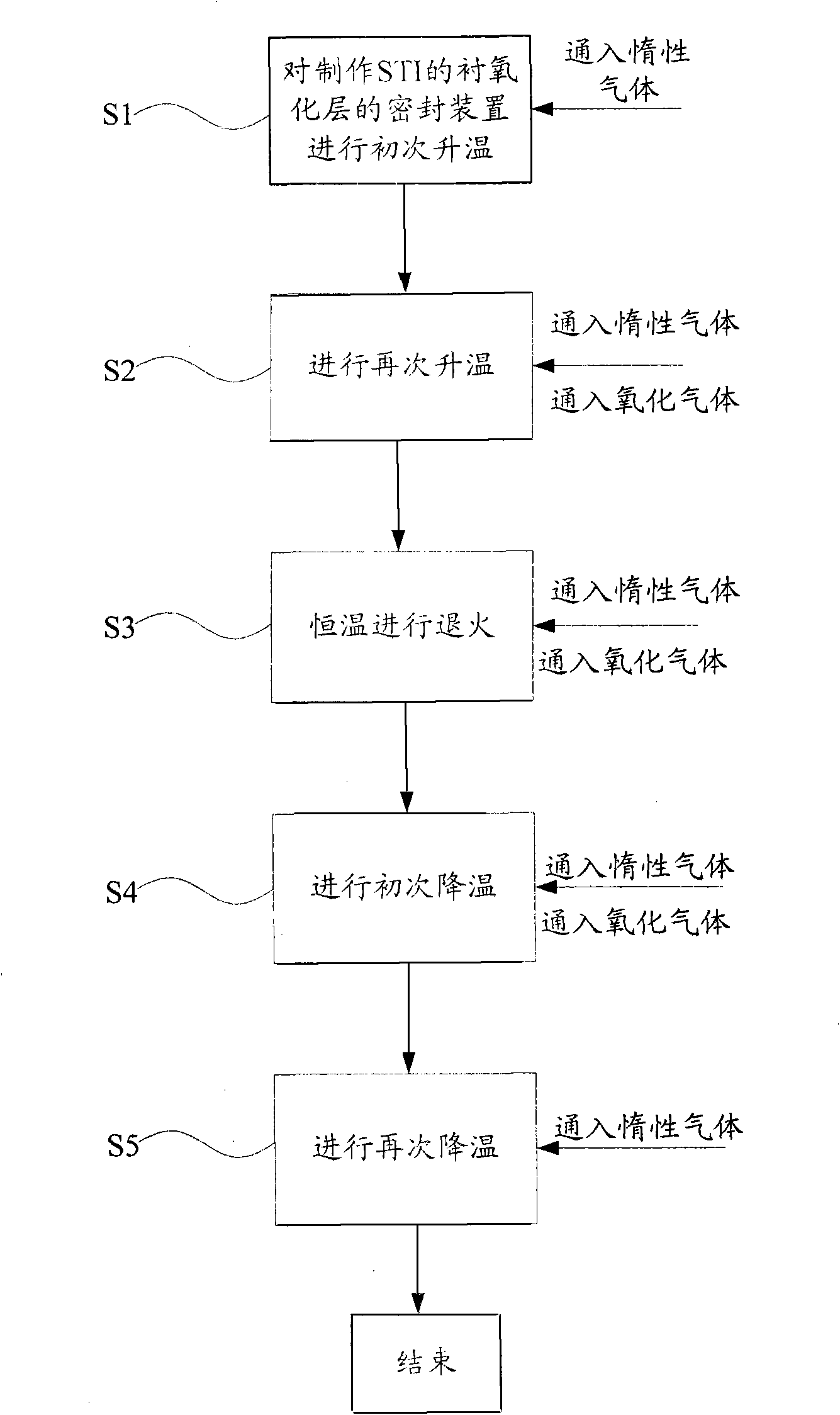
[0009] The lining oxide layer of STI is made by direct oxidation on the etched silicon substrate in the sealing device. The method for making the lining oxide layer of STI of the present invention comprises the following steps: Step 1: Pass the inert gas into the sealing device while heating up for the first time. Gas; step 2: enter the sealing device and heat up again to make it reach the temperature for making the lining oxide layer of STI, and at the same time pass inert gas and oxidizing gas into the sealing device to grow the lining oxide layer of STI. The temperature for making the lining oxide layer of STI is 950-1150 degrees Celsius. In order to better control the temperature of the sealing device, the initial temperature increase in step 1 is greater than the second temperature increase in step 2. In step 1, when the temperature of the sealing device is greatly increased to be close to the fabrication temperature of the STI liner oxide layer, a small increase in temper...


PUM


Abstract

The invention provides a method for producing an STI lining oxide layer which is prepared directly on a silicon substrate etched in a sealing device. The method comprises steps as follows: 1, rising temperature primarily to the sealing device and introducing inert gas; 2, rising temperature again to the sealing device to a temperature for producing the STI lining oxide layer, introducing inert gas and oxidizing gas into the sealing device for growing the SIT lining oxide layer; 3, performing anneal to the STI lining oxide layer, and introducing inert gas and oxidizing gas into the sealing device; 4, reducing temperature primarily to the sealing device and introducing inert gas and oxidizing gas into the sealing device; and 5, reducing temperature again to the sealing device and introducing inert gas into the sealing device. The method can effectively solve the problem of active area damage caused by the traditional production method, and improves the production efficiency as well as the coverage rate of the lining oxide layer.

Description

technical field [0001] The invention relates to the field of STI fabrication, in particular to a method for reducing damage to an active region caused when an STI lining oxide layer is fabricated. Background technique [0002] Shallow Trench Isolation (STI) is a commonly used isolation technology for semiconductor integrated chips at present. STI is made in the isolation device for isolation, and insulators are filled in the shallow trenches to achieve the purpose of insulating the devices to be isolated. The STI structure is usually formed by first depositing a silicon nitride layer on a semiconductor substrate, then patterning the silicon nitride layer to form a hard mask, and then etching the substrate to form steep trenches between adjacent elements. Finally, an insulator is filled in the trench to form an element isolation structure. At present, silicon oxide is usually used as the insulator in the shallow trenches, and the filling of the silicon oxide in the shallow ...

Claims


Application Information

Patent Timeline
IPC IPC(8): H01L21/762H01L21/316
Inventor 唐兆云何有丰白杰
Owner SEMICON MFG INT (SHANGHAI) CORP
Learn More