Integral truss-type offshore wind turbine support structure

A support structure and offshore wind power technology, applied in wind turbine components, wind turbines consistent with the wind direction, wind power generation, etc., can solve the problem of high stress concentration at the connection between the central column and other rods, and vortex induced by cylindrical towers. Problems such as vibration and stress concentration are outstanding, and the effects of rational distribution of stiffness and strength, reduction of stress concentration and fatigue damage rate, and low construction cost are achieved.

Inactive Publication Date: 2009-11-04
OCEAN UNIV OF CHINA
View PDF0 Cites 19 Cited by
  • Summary
  • Abstract
  • Description
  • Claims
  • Application Information

AI Technical Summary

Problems solved by technology

[0009] 2. The construction is difficult and the cycle is long
The piles of the jacket structure are driven into the seabed from the main pile legs of the jacket. Therefore, the installation of the superstructure and the tower must be completed after the pile driving construction, and the construction period is long.
[0011] 3. The problem of stress concentration is prominent
[0012] The central column of the tripod structure has the same diameter and wall thickness as the fan tower, so the rigidity is much greater than other components, which causes high stress concentration at the connection between the central column and other components, resulting in serious fatigue damage
Since there is no offshore wind farm with a jacket structure at present, forged steel connectors are still in the conceptual design stage and have not yet been practically applied
[0013] 4. Cylindrical towers are prone to vortex-induced vibration
Therefore, another disadvantage of cylindrical towers is wind-induced vortex-induced vibrations

Method used


Image

  • Integral truss-type offshore wind turbine support structure

Examples


Embodiment Construction

[0032] The present invention will be described in further detail below in conjunction with the accompanying drawings.

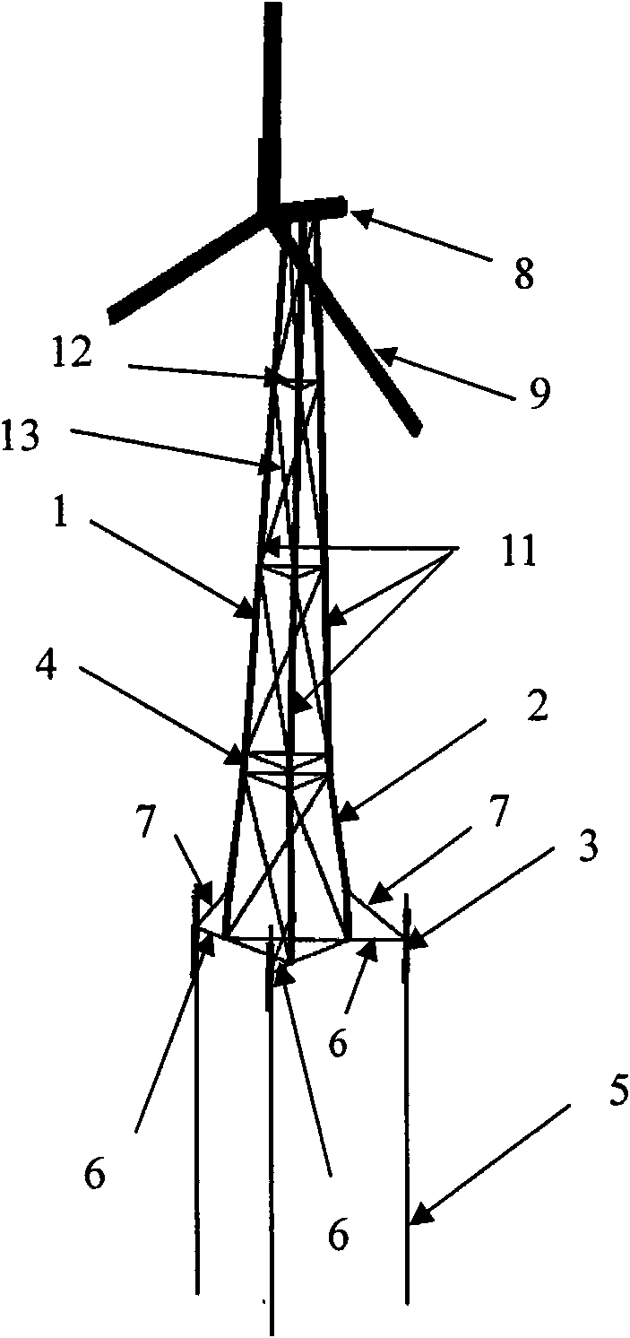
[0033] figure 1 It is a structural schematic diagram of the overall truss-type offshore wind turbine support structure according to the present invention, including three piles 5, and is characterized in that: it also includes a truss-type wind turbine tower 1, a truss-type foundation structure 2, a truss-type wind turbine tower 1, and a truss The basic structure 2 consists of three columns 11 arranged in an equilateral triangle to form an outer frame, and several horizontal struts 12 and diagonal struts 13 are arranged between the columns 11; the truss-type fan tower 1 and the truss-type foundation The flange 4 is connected; the lower end of each column 11 of the truss foundation structure 2 is provided with a leg 3, and the pile leg 3 is connected with the column 11 of the truss foundation structure 2 through the connecting rod A6 and the connecting rod B7,...


PUM


Abstract

An integral truss-type offshore wind turbine support structure relates to the offshore wind turbine field. The support structure comprises three piles. The support structure is characterized by further comprising a truss-type wind turbine tower and a truss-type substructure of an outer frame body, which are composed of three upright posts arranged in equilateral triangles. The truss-type wind turbine tower and the truss-type substructure are connected by a flange, the lower end of each post of the truss-type substructure is provided with a pile leg which is connected with the posts of the truss-type substructure by a connecting rod A and a connecting rod B, the connecting rod A is a horizontal connecting rod positioned between the posts and pile legs, and the connecting rod B is an oblique connecting rod positioned between the posts and the pile legs; and the piles pass through the pile legs to penetrate into submarine soil so as to fix the truss-type substructure on a sea bed, and the upper ends of the piles are fixed with the pile legs by welding. As the integral truss-type structure is adopted as the support structure, the integral truss-type offshore wind turbine support structure has the advantages of good strength utilization ratio of materials, short construction period, low construction cost and structure cost, being suitable for various sea bottom conditions and wide applicable scope of water depth.

Description

technical field [0001] The invention relates to an offshore wind turbine, in particular to an integral truss type offshore wind turbine support structure. Background technique [0002] The support structure of offshore wind turbines is the key structure for the construction of offshore wind farms, and its cost determines whether offshore wind farms can be connected to the grid for power generation and become an alternative energy source for traditional energy sources. [0003] At present, the supporting structures of offshore wind turbines mainly include gravity structures, monopile structures, tripod structures, jacket structures and floating structures. Among them, the maximum water depth applicable to the gravity structure is 10m, the maximum water depth applicable to the single pile structure is 30m, the maximum water depth applicable to the tripod structure is 40m, the maximum water depth applicable to the jacket structure is 50m, and the applicable water depth of the f...

Claims


Application Information

Patent Timeline
Patent Type & Authority Applications(China)
IPC IPC(8): F03D1/00F03D11/00F03D13/25
CPCY02E10/722Y02E10/72Y02E10/727
Inventor 黄维平刘建军韩旭
Owner OCEAN UNIV OF CHINA
Why Eureka
Try Eureka