Wave type headshaking mechanism as well as electric fan and heater using same

A wave-type, crank-link mechanism technology, which is applied to machines/engines, parts of pumping devices for elastic fluids, mechanical equipment, etc., can solve problems such as complex installation structures, complex circuits, and fatigue fractures of shrapnel, and achieve The effect of expanding the wind receiving area, high transmission efficiency and convenient maintenance

Inactive Publication Date: 2009-11-04
曹金财 +1
View PDF2 Cites 5 Cited by
  • Summary
  • Abstract
  • Description
  • Claims
  • Application Information

AI Technical Summary

Problems solved by technology

Although this structure realizes three-dimensional wide-area air supply, the use of synchronous motors increases the number of power sources, complicates the circuit, and accidental overloading can also cause damage to the synchronous motor, greatly reducing the reliability and life of the electric fan. Therefore, the market's approval rate for this type of electric fan is low, and it has not been popularized.
[0004] The second type is single power drive, which is directly driven by the main motor through a single gear box to realize up and down and left and right shaking. Secondary time, the transmission distance of the power transmission mechanism is generally the center distance and must be periodically changed, and the traditional mature mechanism cannot be directly used
However, because the up and down swing of this mechanism is realized by the bending of the shrapnel, the shrapnel is prone to fatigue fracture during frequent bending and straightening, and the reliability is poor.
Therefore, the performance and quality of this kind of flexible parts directly affect the reliability and life of the whole mechanism. It is difficult to choose an ideal flexible part under the existing technical conditions, which restricts the mass production and sales of electric fans using this mechanism.
[0005] The vertical electric fan oscillating device disclosed in Chinese patent ZL92203795.7 also shows a single power to complete the up and down compound oscillating mechanism, the motor shaft is lengthened at the rear of the motor, and a clutch type oscillating control mechanism is horizontally installed between the original horizontal oscillating device , the oscillating head plate, the connecting rod and the Y-shaped bracket constitute a crank-link mechanism. The shaft of the Y-shaped bracket is inserted into the angle plate seat, and the two holes on the upper part of the Y-shaped bracket are hinged to the shaft of the motor housing. Although this mechanism realizes the composite shaking head, but The addition of a clutch device and a two-day linkage link complicates the movement transmission, making it difficult to achieve linkage and difficult for practical application.
[0008] Through analysis, the applicant believes that the wave-type oscillating mechanism of the combined three-dimensional air supply fan generally has a complicated installation structure between the machine head and the machine base, and there are many mechanism parts for driving the machine head to realize the wave-like oscillating head, so the cost of the entire fan is high. , not suitable for consumers to choose

Method used


Image

  • Wave type headshaking mechanism as well as electric fan and heater using same
  • Wave type headshaking mechanism as well as electric fan and heater using same
  • Wave type headshaking mechanism as well as electric fan and heater using same

Examples


Embodiment 1

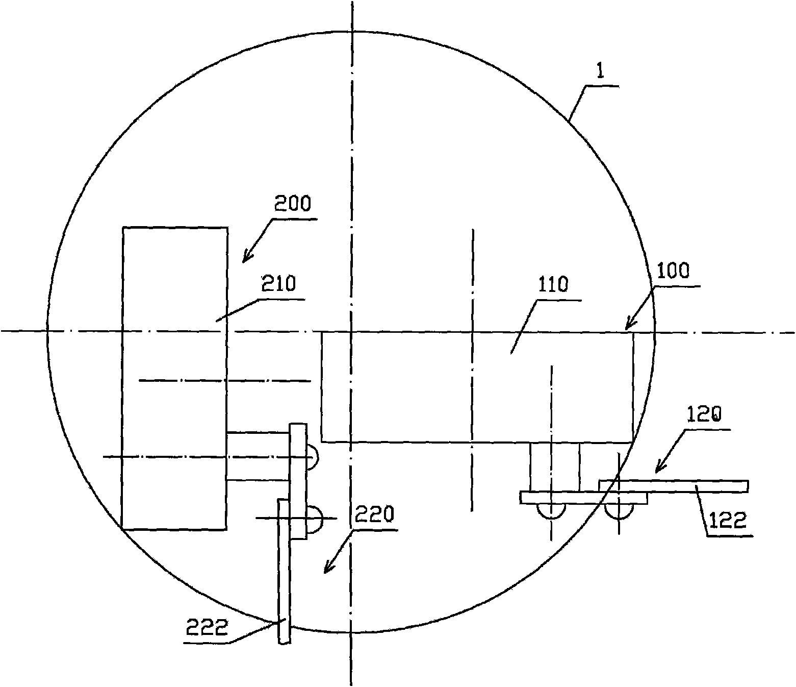
[0052] see figure 2 , figure 2 The first oscillating mechanism 100 and the second oscillating mechanism 200 are all motor type. The first oscillating mechanism 100 is composed of a geared motor 110 installed in the machine head 1 and a crank linkage mechanism 120 installed on the output shaft of the geared motor 110. The other end of the connecting rod 122 of the crank linkage mechanism 120 stretches out of the machine head 1 Outer hinges with 2 bases. The first oscillating mechanism 100 can realize the left and right oscillating head of the machine head 1 .

[0053] The second oscillating mechanism 200 is composed of a gear motor 210 installed in the machine head 1 and a crank linkage mechanism 220 installed on the output shaft of the gear motor 210. The other end of the connecting rod 222 of the crank linkage mechanism 220 stretches out of the machine head 1 Outer hinges with 2 bases. The second oscillating mechanism 200 can realize the up and down oscillating of the m...

Embodiment 3

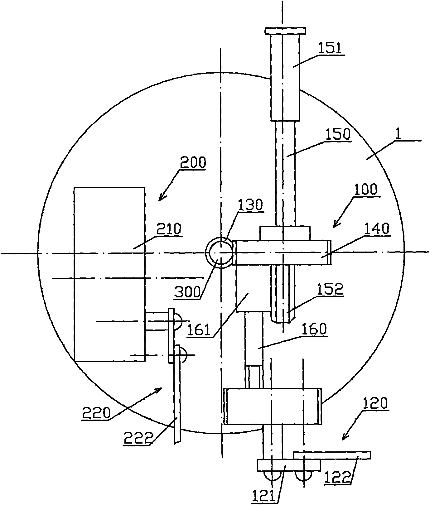
[0056] see image 3 , image 3 The first oscillating mechanism 100 is mechanical, and the second oscillating mechanism 200 is electromechanical. A main motor (not shown in the figure) that drives the fan to rotate is arranged in the machine head 1 .

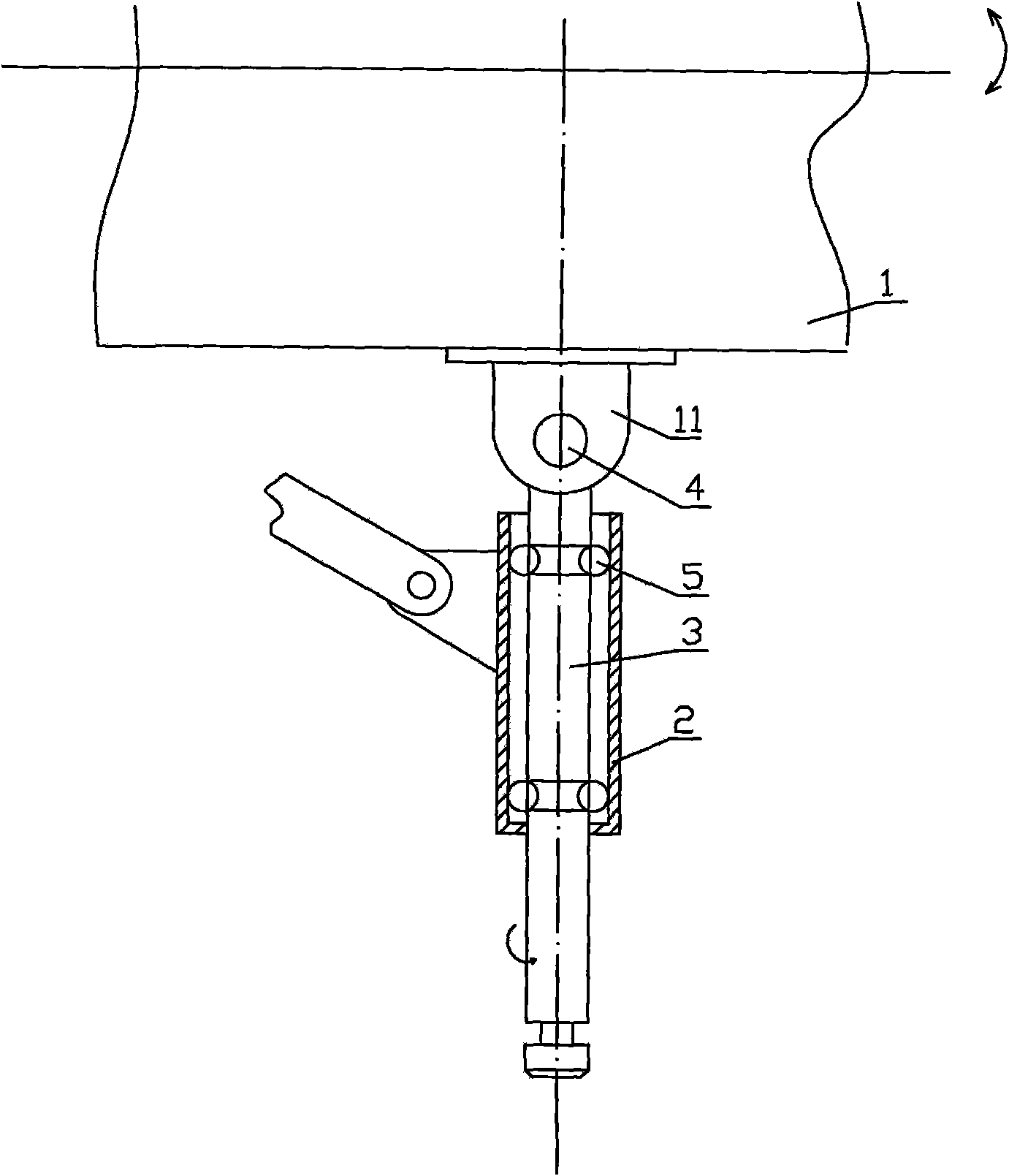
[0057] The first shaking head mechanism 100 comprises a worm screw 130, a worm wheel 140, a clutch puller 150, a gear shaft 160, and a crank linkage mechanism 120; In the machine head 1, the worm gear 140 is sleeved on the middle part of the clutch puller 150 and meshed with the worm screw 130, so that when the power output shaft 300 of the main motor rotates, the worm gear 140 is driven to rotate by the worm screw 130.

[0058] The middle part of the clutch lever 150 is also provided with clutch external teeth, and one end of the clutch lever 150 protrudes out of the machine head 1 and is provided with a toggle handle 151, and the other end of the clutch lever 151 is provided with a driving gear 152, inside the worm wheel 140 ...

Embodiment 4

[0072] see Figure 5 , Figure 5 The second oscillating mechanism 200 in is all motor type. The second oscillating mechanism 200 is composed of a gear motor 210 installed in the machine head 1 and a crank linkage mechanism 220 installed on the output shaft of the gear motor 210. The other end of the connecting rod 222 of the crank linkage mechanism 220 stretches out of the machine head 1 Outer hinges with 2 bases. The second oscillating mechanism 200 can realize the independent up and down oscillating of the machine head 1 .

[0073] The decelerating motor 220 in the second shaking head mechanism 200 can be controlled by an independent switch (not shown in the figure) arranged on the machine base 2, so as to realize shaking the head up and down,

[0074] The wave-type shaking head mechanism of the above-mentioned embodiment can be used to make a wave-type shaking head electric fan. The fan cover of the existing electric fan is installed on the machine head 1, and the fan le...


PUM


Abstract

A wave type headshaking mechanism comprises a machine head, a stand for carrying the machine head, a first headshaking mechanism which leftwards and rightwards drives the machine head to shake head and a second headshaking mechanism which drives the machine head up and down, and the first headshaking mechanism and the second headshaking mechanism are arranged in the machine head and are connected with the stand. The wave type headshaking mechanism also comprises a rotating shaft, and the upper end of the rotating shaft is articulated with the machine head through a pin shaft in order to enable the machine head to swing up and down along the shaft line of the pin shaft under the driving of the second headshaking mechanism. The shaft body of the rotating shaft is connected with the stand through a block bearing in order to enable the machine head to swing leftwards and rightwards along the shaft line of the pin shaft under the driving of the first headshaking mechanism. The invention also provides an electric fan or a heater which uses the wave type headshaking device. A simple device is used by the invention to realize the left and right head shaking and the up and down head shaking of the machine head, and the winding area of the electric fan and the heating area of the heater are enlarged. The invention has the advantages of high transmission efficiency, convenient repair and low cost.

Description

technical field [0001] The invention relates to an oscillating mechanism used in electric fans and heaters, in particular to a wave-type oscillating mechanism. The invention also relates to an electric fan and a heater using the wave-type oscillating mechanism. Background technique [0002] The electric fans and heaters sold on the existing market generally only do a single left-right shaking action, which can be combined with manual adjustment of the head pitch to adjust the pitch angle of the head to change the wind area, but the pitch angle of the head is often fixed during normal operation. However, it only relies on the left and right swing of the machine head itself to send air or heat, so the wind receiving area is limited. [0003] There are now combined three-dimensional air-supply electric fans on the market. There are two ways to realize this type of electric fan. One is driven by two powers to drive the left and right swing heads and up and down swing heads of t...

Claims


Application Information

Patent Timeline
Patent Type & Authority Applications(China)
IPC IPC(8): F04D29/00F04D25/10
Inventor 曹金财森川静子
Owner 曹金财
Why Eureka
Try Eureka