Method for calibrating wave front of self-adaptive optical loop

A technology of adaptive optics and wavefront, applied in the field of adaptive optics, can solve problems such as heavy workload, affecting the correction effect, laser system restricting the conjugate relationship of objects and images, etc.

Inactive Publication Date: 2009-11-04
SHANGHAI INST OF OPTICS & FINE MECHANICS CHINESE ACAD OF SCI
View PDF0 Cites 15 Cited by
  • Summary
  • Abstract
  • Description
  • Claims
  • Application Information

AI Technical Summary

Problems solved by technology

This not only brings a large workload to the experiment, but also introduces additional errors. At the same time, in the case of using off-axis parabolic mirrors with different focal lengths, whether there is always a suitable position for the deformation mirror at the front end of the system is also an unavoidable big problem. question
[0014] In short, the aperture limitation of the wavefront measurement tool and the complexity of the laser system greatly restrict the convenient formation of the object-image conjugate relationship
At the same time, the position of the object image under different deformable mirrors is different, which brings troubles to the experiment and ultimately affects the correction effect
Moreover, the different optical path layouts of different laser systems to be corrected further complicate the existing problems

Method used


Image

  • Method for calibrating wave front of self-adaptive optical loop
  • Method for calibrating wave front of self-adaptive optical loop
  • Method for calibrating wave front of self-adaptive optical loop

Examples


specific Embodiment approach

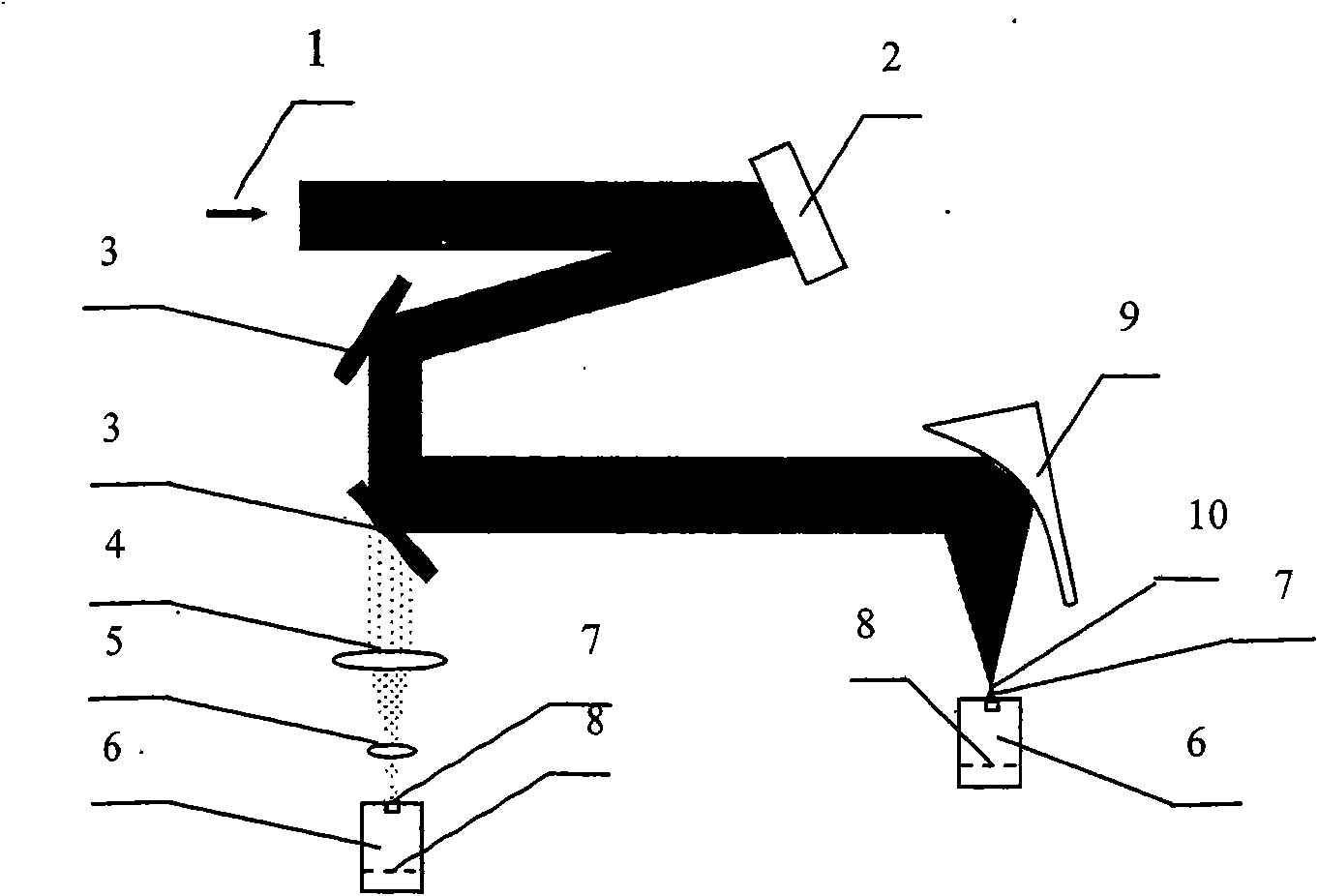
[0063] Considering that the correction method of the present invention is the sublation of the traditional correction method, therefore, in order to compare the correction idea of ​​the present invention—the adaptive optics loop calibration wavefront method based on Fresnel diffraction theory—,

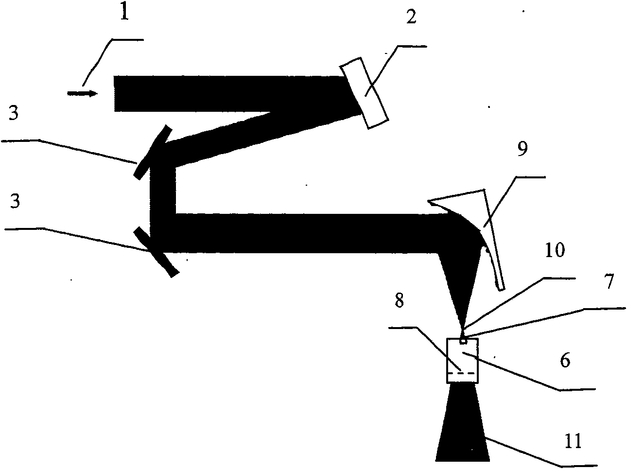
[0064] The structural diagram of the adaptive optics loop calibration wavefront method based on the Fresnel diffraction theory of the present invention is as follows figure 2 shown, with figure 1 In contrast, although the correction optical path is basically similar, many limitations and difficulties in the past correction methods have been overcome due to the introduction of Fresnel diffraction theory.

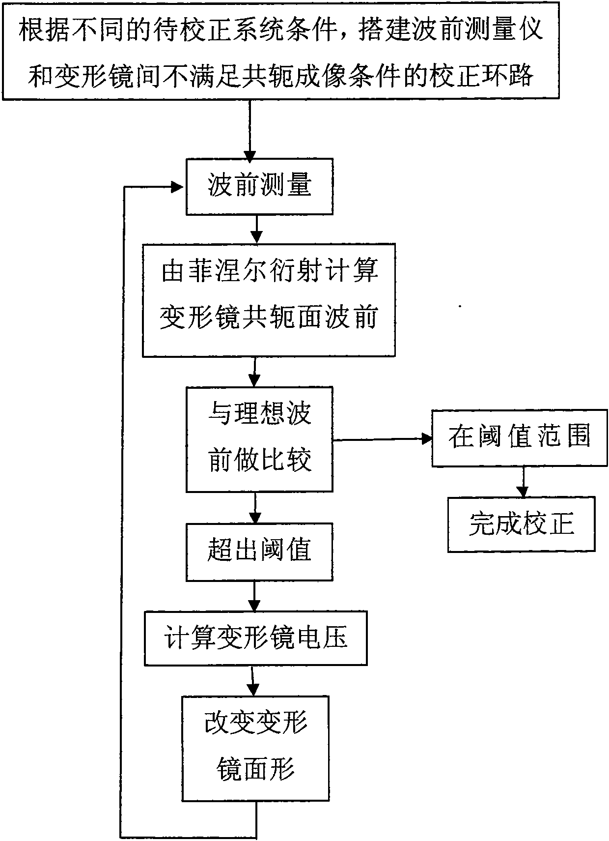
[0065] Adaptive optics loop calibration wavefront method of the present invention such as image 3 shown, including the following steps:

[0066] (1) install the wavefront measuring instrument 6 at any beam position where the spot size of the beam to be measured does not exceed th...


PUM


Abstract

The invention relates to a method for calibrating the wave front of a self-adaptive optical loop. The method is to utilize the Fresnel diffraction theory and use computer programming to process wave front phase and amplitude distribution, which is measured in a certain position of an optical path, on a vertical optical axial plane, obtain phase and amplitude distribution of a conjugate plane of a distorting lens, take the computed value as a basis to change the surface shape of the distorting lens, and achieve the aim of wave front compensation. The method greatly increases the flexibility of the placing position of the distorting lens in the optical path, so that the complexity of the optical path can be effectively reduced and convenience is provided for wave front calibration comprising wave front pre-calibration. Therefore, the method has important practical value.

Description

technical field [0001] The invention relates to adaptive optics, in particular to a method for calibrating wavefronts by an adaptive optics loop. On the basis of measurement, it is a method to easily obtain the wavefront information of any position and size of light wave in the near field through computer programming processing, so that it is more convenient to provide the wavefront to be corrected for the deformable mirror loop correction wavefront previous information, especially phase information. Background technique [0002] Ultra-short and ultra-intense laser science is an important frontier field of science, focusing on the development of ultra-short and ultra-intense laser technology, the interaction between ultra-short and ultra-intensive lasers and matter, and cutting-edge basic research in interdisciplinary and related high-tech fields. , is the basis for realizing extreme physical conditions and revealing the essence of matter. [0003] Ultra-short and ultra-in...

Claims


Application Information

Patent Timeline
Patent Type & Authority Applications(China)
IPC IPC(8): G02B26/06
Inventor 任志君梁晓燕刘美标李儒新徐至展
Owner SHANGHAI INST OF OPTICS & FINE MECHANICS CHINESE ACAD OF SCI
Why Eureka
Try Eureka