Non-contact method for dehumidifying liquid and dehumidifier

A liquid dehumidification, non-contact technology, applied in separation methods, chemical instruments and methods, and separation of dispersed particles, etc., can solve problems such as living room, furniture corrosion, and adverse effects on human health, to strengthen the dehumidification process and regeneration process, improve The effect of system performance

Inactive Publication Date: 2009-11-11
SOUTH CHINA UNIV OF TECH
View PDF0 Cites 27 Cited by
  • Summary
  • Abstract
  • Description
  • Claims
  • Application Information

AI Technical Summary

Problems solved by technology

However, the inherent disadvantage of liquid dehumidification technology is that the dehumidified air will entrain the salt in the solution...

Method used


Image

  • Non-contact method for dehumidifying liquid and dehumidifier
  • Non-contact method for dehumidifying liquid and dehumidifier
  • Non-contact method for dehumidifying liquid and dehumidifier

Examples


Embodiment 1

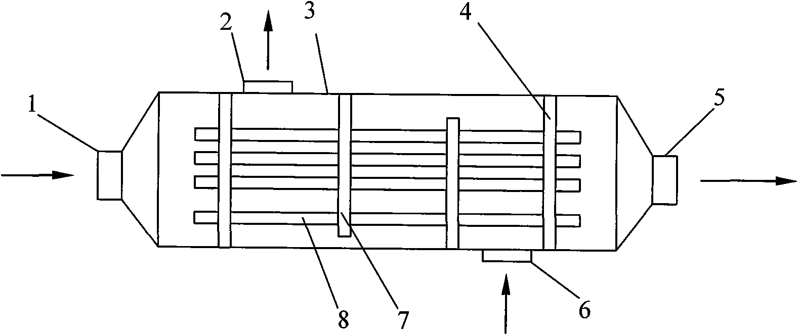
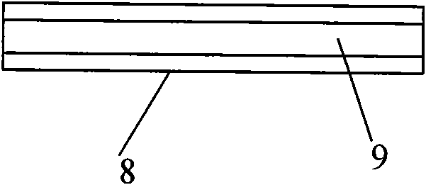
[0025] Hollow fiber or tubular membrane dehumidifier structure such as figure 1 shown by figure 1 It can be seen that the dehumidification salt solution (such as lithium chloride solution, lithium bromide solution, etc.) inlet flow channel 1 of the membrane dehumidifier is connected with the left end of the shell 3, the outlet flow channel 5 of the dehumidification salt solution is connected with the right end of the shell 3, and the dehumidification air inlet flow channel 6 is connected to the opening on the lower right side of the housing 3 , and the dehumidified air outlet channel 2 is connected to the opening on the upper left side of the housing 3 . The head 4 is placed at both ends of the shell, and the left and right ends of the shell are blocked. There are many holes on it, and a plurality of hollow fibers or tubular membranes 8 pass through the head 4 through these holes and are fixed inside the shell. . The fluid inside the tube is called the tube side, and the flu...

Embodiment 2

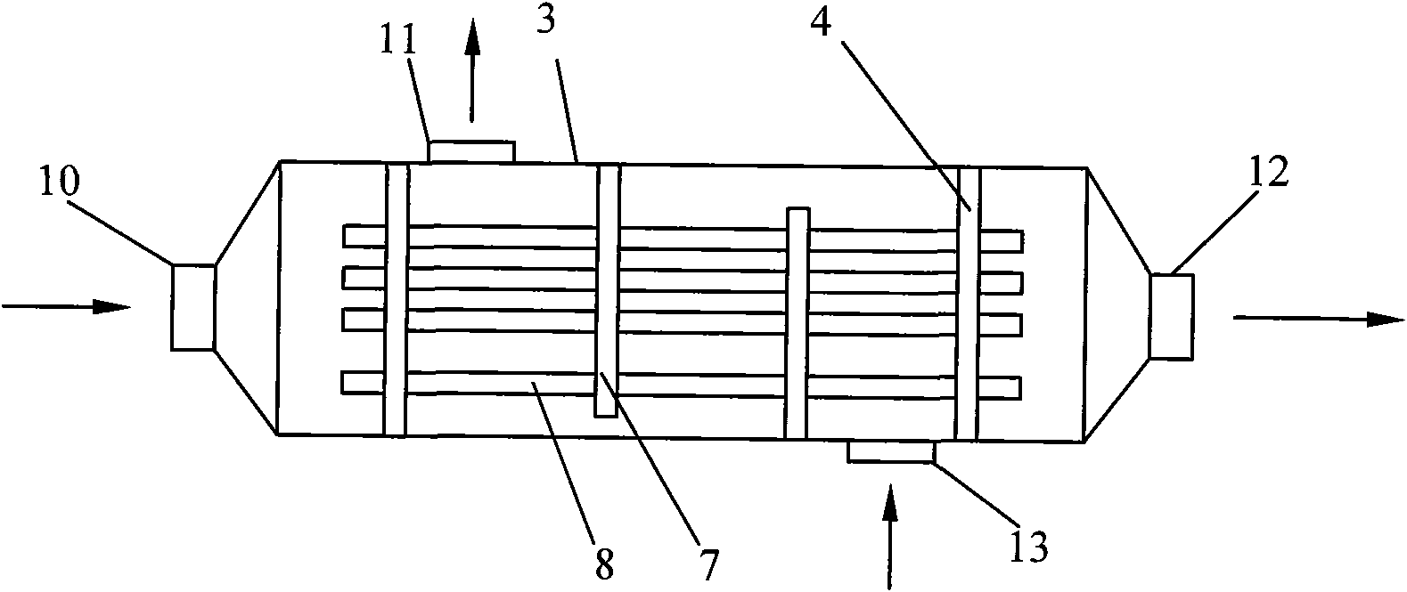
[0030] The hollow fiber or tubular membrane dehumidifiers of the present invention can also be used as regenerators. structured as image 3 shown by image 3 It can be seen that when used as a regenerator, the inlet channel 13 of the regenerated salt solution (such as lithium chloride solution, lithium bromide solution, etc.) is connected to the lower right end of the housing 3, and the outlet channel 11 of the regenerated salt solution is connected to the upper left end of the housing 3. The air inlet channel 10 is connected to the left side of the housing 3 , and the regeneration air outlet channel 12 is connected to the right side of the housing 3 . The head 4 is placed at both ends of the housing to seal the two sides of the housing. There are multiple holes on it, and the hollow fiber or tubular membrane 8 passes through the openings of the head 4 and is fixed inside the housing. The fluid inside the tube is called the tube side, and the fluid outside the tube is called...

Embodiment 3

[0034] The structure of flat membrane dehumidifier of the present invention is as Figure 4 shown by Figure 4 It can be seen that the flat membrane dehumidifier and regenerator of the present invention are connected to the left side of the housing 3 by the inlet channel 14 of the salt solution (such as lithium chloride solution, lithium bromide solution, etc.), and the outlet channel 16 of the salt solution is connected to the right side of the housing 3. The air inlet channel 15 is connected to the upper end of the housing 3 , and the air outlet channel 18 is connected to the lower end of the housing 3 . A core body 17 made of parallel plate film is placed in the casing 3 . The structure of the core is as Figure 5 As shown, the core body is formed by stacking multi-layer flat membranes, and each layer of flat membranes is separated by a partition to form a hollow layer. The opposite sides of the hollow layer are blocked by sealing plates 20 to prevent fluid leakage, and t...


PUM


Abstract

The invention provides a non-contact method for dehumidifying liquid and a dehumidifier. The method comprises the following steps that: dehumidifying saline solution and air are separated by a membrane; when the air flows from the surface on one side of the membrane, water vapor in the air passes through the membrane selectively to reach the other side of the membrane; and then, the water vapor is absorbed by the dehumidifying saline solution contacted with the membrane, but salt molecules and liquid water cannot pass through the membrane so as to dry the air. The dehumidifier comprises a shell, an air passage and a saline solution passage, wherein the air passage and the saline solution passage are separated by the membrane; and the membrane is placed in the shell, and is a permselective membrane, so that the water vapor can pass through the membrane but the saline solution cannot pass through the membrane. The method and the dehumidifier can effectively prevent salt in the solution from being brought into the air, thereby preventing occurrence of corrosion.

Description

technical field [0001] The invention relates to liquid dehumidification technology, in particular to a non-contact liquid dehumidification method and a dehumidifier in the field of air conditioning. Background technique [0002] In recent years, with the development of my country's society and economy, people's living standards have been continuously improved, and higher requirements have been put forward for the comfort of the living environment, among which the demand for dehumidification has become stronger and stronger; in some special departments, such as archives, Tobacco, military industry, medicine, etc., as well as underground or semi-underground buildings, etc., also have higher dehumidification requirements according to different uses. Air conditioning includes the adjustment of temperature and humidity. Among them, dehumidification is a high energy consumption work. The energy consumption of air-conditioning accounts for 20% to 40% of the total energy consumption...

Claims


Application Information

Patent Timeline
IPC IPC(8): B01D53/26B01D53/22
Inventor 张立志
Owner SOUTH CHINA UNIV OF TECH
Why Eureka
Try Eureka