LED flashlight

A technology of LED flashlight and handle, applied in the field of LED flashlight

Inactive Publication Date: 2009-11-18
赖斌
View PDF0 Cites 12 Cited by
  • Summary
  • Abstract
  • Description
  • Claims
  • Application Information

AI Technical Summary

Problems solved by technology

Poor

Method used


Image

  • LED flashlight
  • LED flashlight
  • LED flashlight

Examples


Embodiment 1

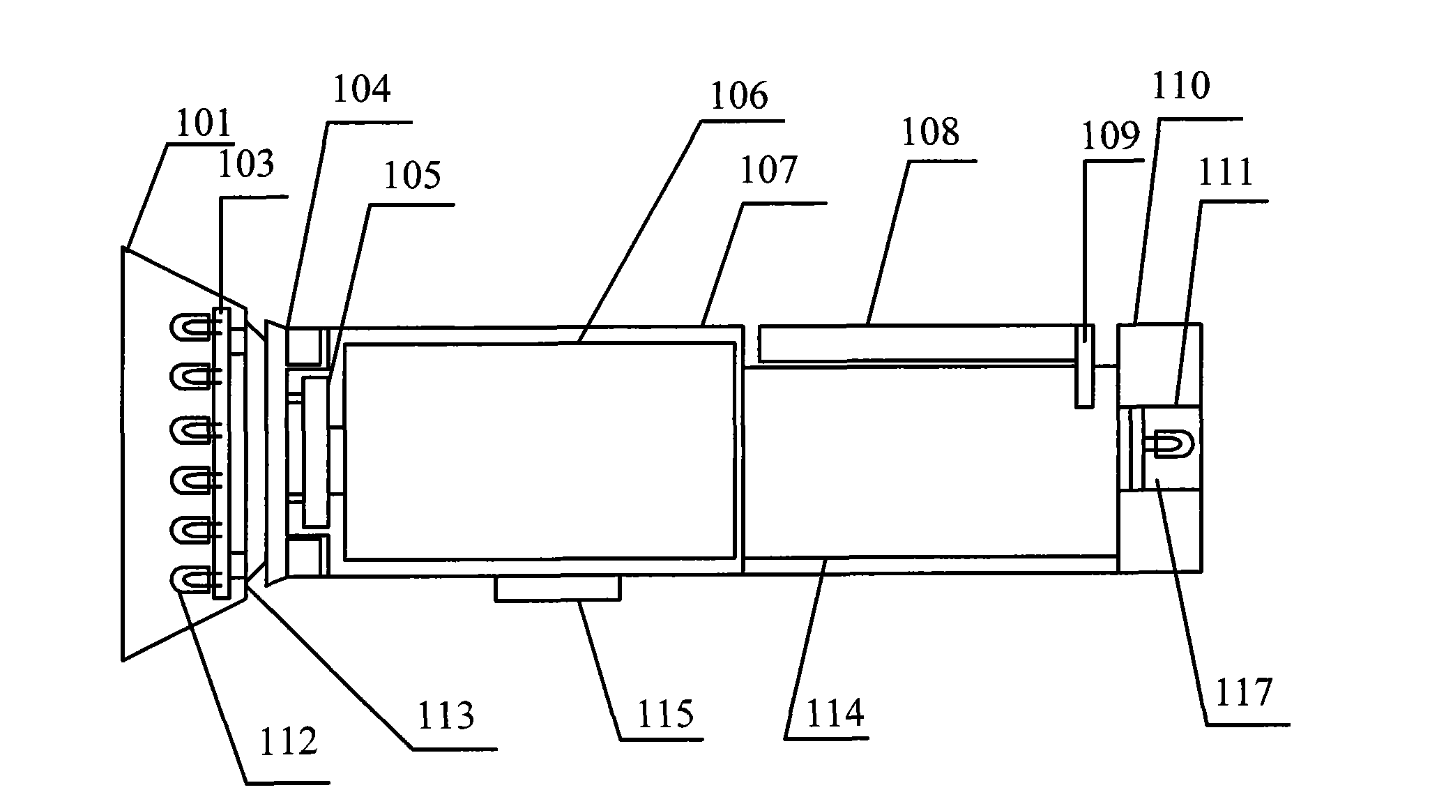
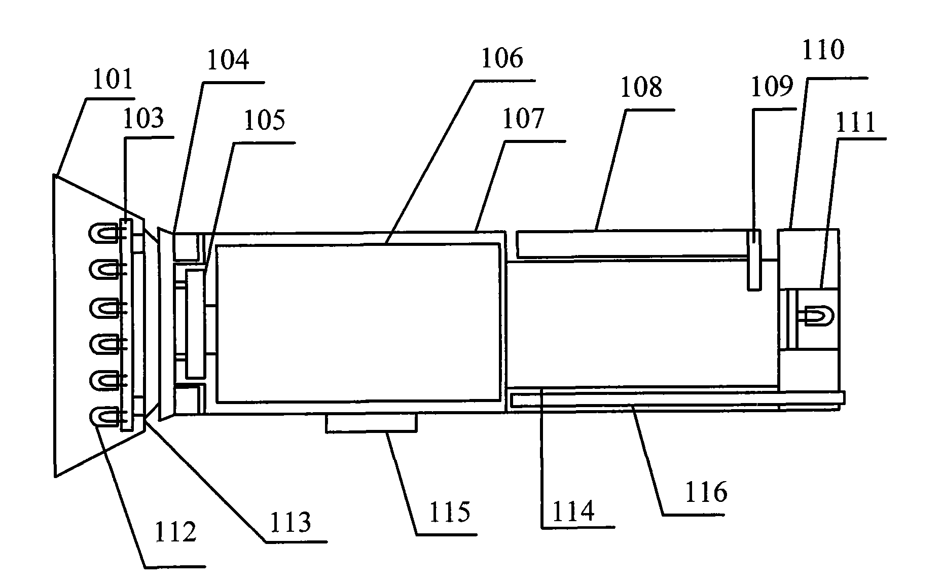
[0030] like figure 1 As shown, this embodiment provides an LED flashlight, including a first light emitting device 101, a second light emitting device 111, a column 107, a first control switch 115 and a control circuit thereof; the first light emitting device 101 is arranged on the The first end of the cylinder 107 includes a lamp holder, a heat dissipation layer, at least one PCB board 103, at least one LED light emitting diode 112 and its control device.

[0031] The PCB board 103 is fixed on the lamp holder, for example, fixed on the lamp holder by screws.

[0032] The heat dissipation layer is arranged between the PCB board 103 and the lamp holder, for example, the heat dissipation layer and the PCB board are non-conductively arranged closely, and the heat dissipation layer is arranged closely or between the lamp holder Leave a gap.

[0033] The lamp holder is fixedly connected to the cylinder 107 through a connection device; the connection device can be implemented in v...

Embodiment 2

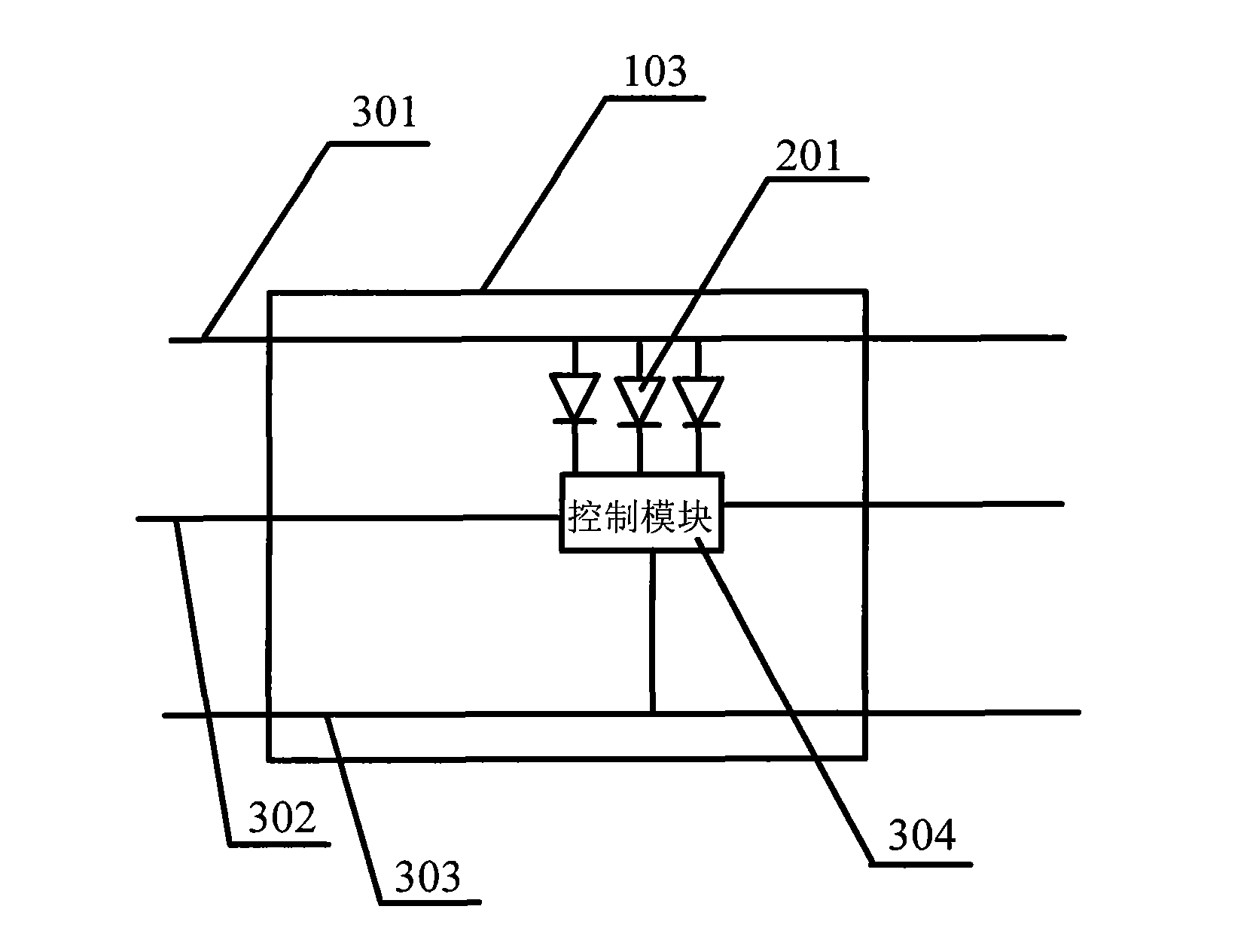
[0051] On the basis of each example in Embodiment 1, a plurality of positive power lines and a plurality of negative power lines may also be arranged on the PCB 103 .

[0052] Each power supply line can be set to include multiple positive power supply lines and multiple negative power supply lines, each positive power supply line and each negative power supply line are respectively connected to an external power supply, and are used to provide voltage for each group of LED light-emitting diodes 201, so as to ensure that the LED The normal operation of each group of LED light-emitting diodes and other electronic components in the device; other electronic components can be control devices, or resistors installed to prevent excessive current.

[0053] Set up multiple pairs of positive and negative power lines, which can be connected to LED light-emitting diodes and other electronic components. When a certain pair of positive and negative power lines is disconnected, it will not af...

Embodiment 3

[0065] On the basis of the above examples, a heat dissipation layer can also be provided between the PCB board 103 and the lamp holder in the first light emitting device 101. The heat dissipation layer is a metal substrate, such as aluminum, copper, etc., and the metal substrate can be provided independently. Because metal has a very good heat conduction function, therefore, the heat in the lamp body can be exported through the heat dissipation layer; in addition, the heat dissipation layer can also be integrally formed with the PCB board 103, that is, the heat dissipation layer and the PCB board are set as an integral composite plate, which can The heat in the lamp body can be better transferred to the heat dissipation layer through the PCB board, and then exported from the heat dissipation layer; in addition, the PCB board can also be directly set as a metal PCB board with heat conduction function, such as aluminum-based PCB board, copper-based PCB board etc., the heat in the...


PUM


Abstract

The invention discloses an LED flashlight, comprising a first irradiation device, a second irradiation device, a control switch, a column body, a battery, a manual power generation device and a control device; the first irradiation device is arranged at the front end of the column body and is connected with the column body via a connection device; the second irradiation device is arranged at the rear end of the column body and is integrated with the column body in design; a chargeable battery, the power generation device and the control device are arranged inside the column body; the control switch and the handle device are arranged on the surface of the column body; the chargeable battery, the power generation device, the control device and the control switch are electrically connected in sequence via lead wires, and the control device is used for, when satisfying preset conditions, starting up the control switch and sending a preset control signal to the LED light-emitting diode. The invention can generate power independently and receive and send information, is provided with a front lamp cap and a rear lamp cap, and has the advantages of convenient use, long service life and multifunction.

Description

technical field [0001] The invention relates to an LED lighting device, in particular to an LED flashlight. Background technique [0002] Due to the characteristics of LED lighting, high light source, no radiation, and low power consumption, LED semiconductor light sources have been widely used in the field of lighting decoration in recent years. In the prior art, due to lighting needs, LED flashlights generally use high-power LED light-emitting diodes. , High-power LED light-emitting diodes generate more heat due to their relatively high power, and many existing LED flashlights are relatively rough in production, relatively single in form, and poor in ornamental value. Therefore, there are defects in the prior art and need to be improved. Sex is poor. Contents of the invention [0003] The technical problem to be solved by the present invention is to provide an LED flashlight with simple structure, beautiful appearance and long service life. [0004] The technical solu...

Claims


Application Information

Patent Timeline
IPC IPC(8): F21L4/00F21V23/00F21V19/00H05B37/02F21Y101/02F21Y115/15
Inventor 商松
Owner 赖斌
Why Eureka
Try Eureka