Supercharge Your Innovation With Domain-Expert AI Agents!

Bistable permanent magnetism operating mechanism control circuit

A permanent magnet operating and control circuit technology, applied in the direction of circuits, electric switches, electrical components, etc., to achieve the effects of reducing weight, reducing charging voltage, and reducing temperature rise

Active Publication Date: 2011-06-01
WUHAN NARI LIABILITY OF STATE GRID ELECTRIC POWER RES INST
View PDF0 Cites 0 Cited by
  • Summary
  • Abstract
  • Description
  • Claims
  • Application Information

AI Technical Summary

Problems solved by technology

However, the current control circuit limits the bistable permanent magnet actuator to meet all the above requirements

Method used


Image

  • Bistable permanent magnetism operating mechanism control circuit
  • Bistable permanent magnetism operating mechanism control circuit
  • Bistable permanent magnetism operating mechanism control circuit

Examples


Embodiment Construction

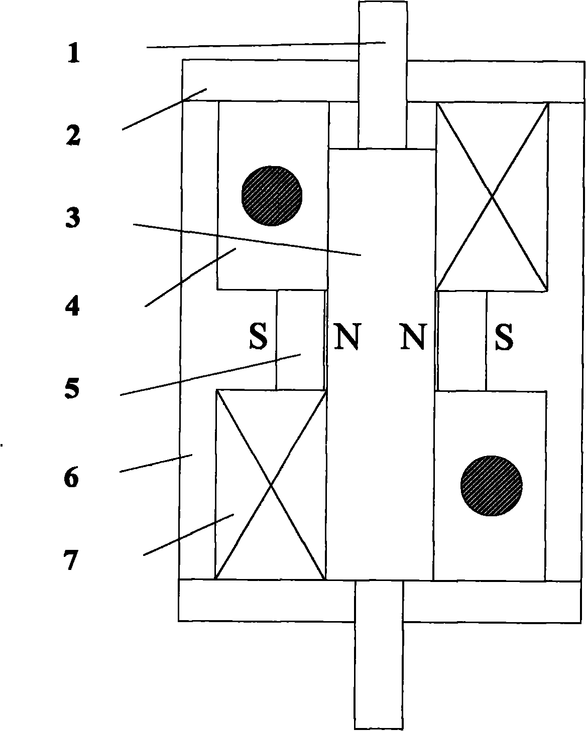
[0012] figure 2 In the description of the mark, the moving guide rod 1, the end cover 2, the moving iron core 3, the opening coil 4, the permanent magnet 5, the yoke 6, and the closing coil 7.

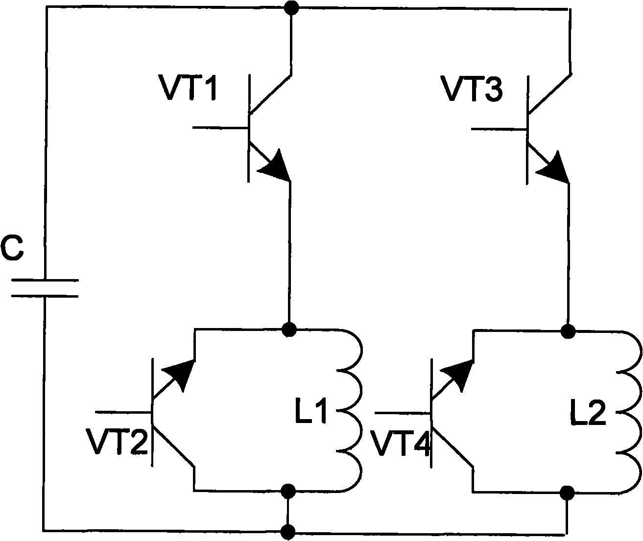
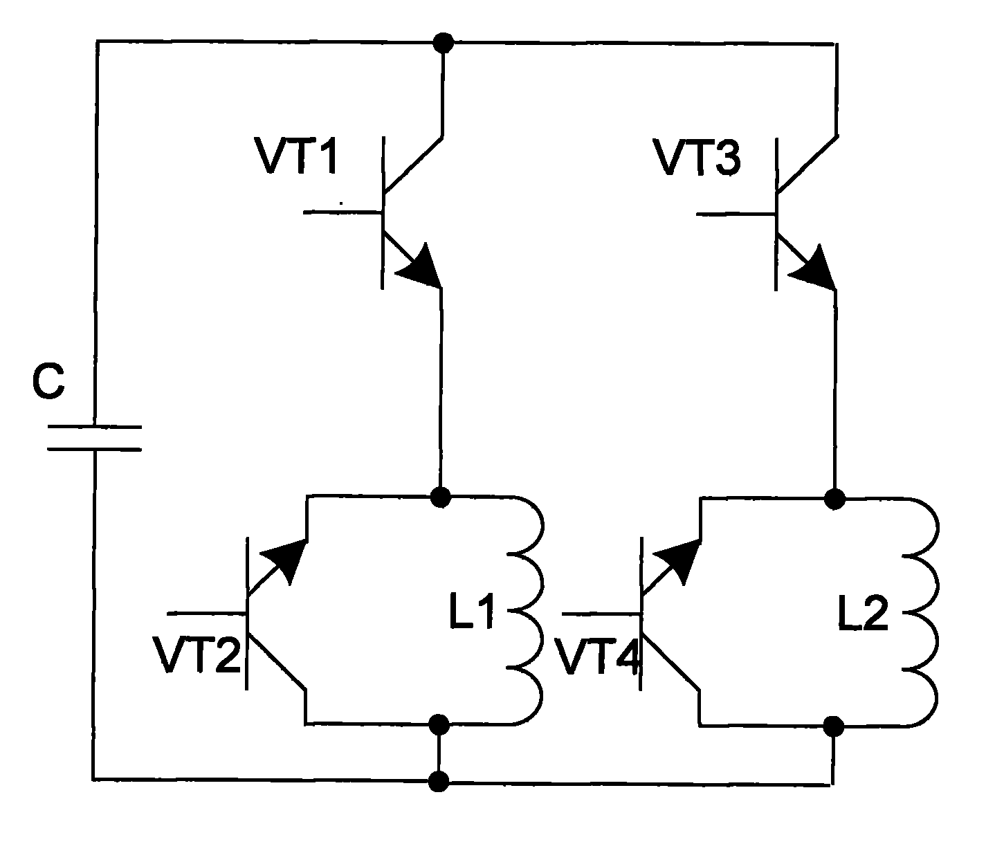
[0013] see figure 1 , a bistable permanent magnet operating mechanism control circuit, comprising a capacitor C, an opening coil (i.e. L1), a closing coil (i.e. L2), switching tubes VT1, VT3, characterized in that it also includes switching tubes VT2 and VT4, wherein, the collectors of the switching tubes VT1 and VT4 are respectively connected to both ends of the capacitor C; the emitters of the two are respectively connected to the emitters of the switching tubes VT2 and VT3; the collectors of the switching tubes VT2 and VT3 are respectively It is connected with the collectors of the switching tubes VT1 and VT4; the two ends of the opening coil are respectively connected with the collector and the emitter of the switching tube VT2; the two ends of the closing coil are respectively c...


PUM


Abstract

The invention relates to a bistable permanent magnetism operating mechanism control circuit and belongs to the electrical equipment technical field. The control circuit comprises a capacitance C, a tripping coil, a closing coil and controlled switching tube VT1 and VT3; the invention is characterized by replacing traditional freewheel diodes by controlled switching tube VT2 and VT4. The control circuit has the advantages that firstly, the coil volume is greatly reduced so that the design of mechanism can be smaller; secondly, the response time can be decreased so that the working speed of mechanism can be improved; thirdly, the capacity or precharge pressure of the capacitance can be reduced.

Description

technical field [0001] The invention relates to a control circuit of a bistable permanent magnet operating mechanism, which belongs to the technical field of electric equipment. Background technique [0002] The bistable permanent magnet operating mechanism has been used more and more in the field of power switches, especially in vacuum circuit breakers. With the increase of high-voltage and ultra-high voltage AC transmission projects, higher requirements are put forward for the bistable permanent magnet operating mechanism. Not only requires the bistable permanent magnet operating mechanism to respond quickly, have small time dispersion, and realize synchronous opening and closing, but also requires the mechanism to be operated with a low-power power supply. At the same time, in order to adapt to the existing design of the power system switch cabinet, it is also necessary The organization is as small as possible. However, the current control circuit limits the bistable pe...

Claims


Application Information

Patent Timeline
Patent Type & Authority Patents(China)
IPC IPC(8): H01H3/28H01H33/38
Inventor 赵军张冰柳欢欢刘飞
Owner WUHAN NARI LIABILITY OF STATE GRID ELECTRIC POWER RES INST
Features
  • R&D
  • Intellectual Property
  • Life Sciences
  • Materials
  • Tech Scout
  • Unparalleled Data Quality
  • Higher Quality Content
  • 60% Fewer Hallucinations
Learn More