New axial center type knee joint prosthesis

A knee joint prosthesis and axis technology, applied in the directions of knee joint, prosthesis, elbow joint, etc., can solve problems such as cavity generation, loosening, susceptibility to infection, etc., achieve structural or functional improvement, increase contact surface, stabilize good effect

Active Publication Date: 2009-11-25
BEIJING CHUNLIZHENGDA MEDICAL INSTR
View PDF0 Cites 11 Cited by
  • Summary
  • Abstract
  • Description
  • Claims
  • Application Information

AI Technical Summary

Problems solved by technology

[0003] Although the above-mentioned hinged knee joint prosthesis can be used as a substitute for the patient's knee joint, it is indeed progressive, but in actual use, it is found that it still has some shortcomings, causing the hinged knee joint prosthesis to fail to achieve The best use effect, and its disadvantages can be summarized as follows:
[0004] 1. The femur and tibia still have the function of internal and external rotation during the process of extension and flexion of the human knee joint, while the hinged knee prosthesis has no rotation function. Therefore, the prosthesis will be subjected to torsion for a long time in the body, which is easy to damage or loosen the prosthesis , and even lead to reoperation;
[0005] 2. The hinged knee prosthesis is made of metal as a whole. Generally, bionic shapes cannot be used, otherwise the prosthesis is too heavy. If the prosthesis is made small, it may sink after implantation, resulting in a cavity, which is easy to be infected and is not beautiful. also not practical
[0006] It can be seen that the above-mentioned existing hinged knee joint prosthesis obviously still has inconvenience and defects in structure and use, and needs to be further improved urgently.

Method used


Image

  • New axial center type knee joint prosthesis
  • New axial center type knee joint prosthesis

Examples


Embodiment Construction

[0026] In order to further explain the technical means and effects that the present invention adopts to achieve the intended purpose of the invention, below in conjunction with the accompanying drawings and preferred embodiments, the specific implementation, structure, Features and their functions are described in detail below.

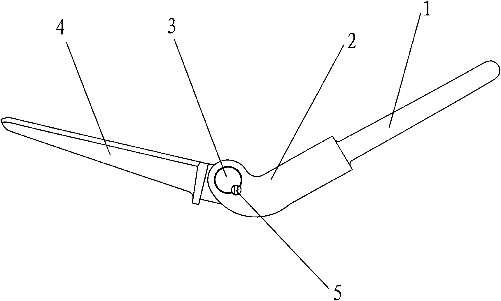
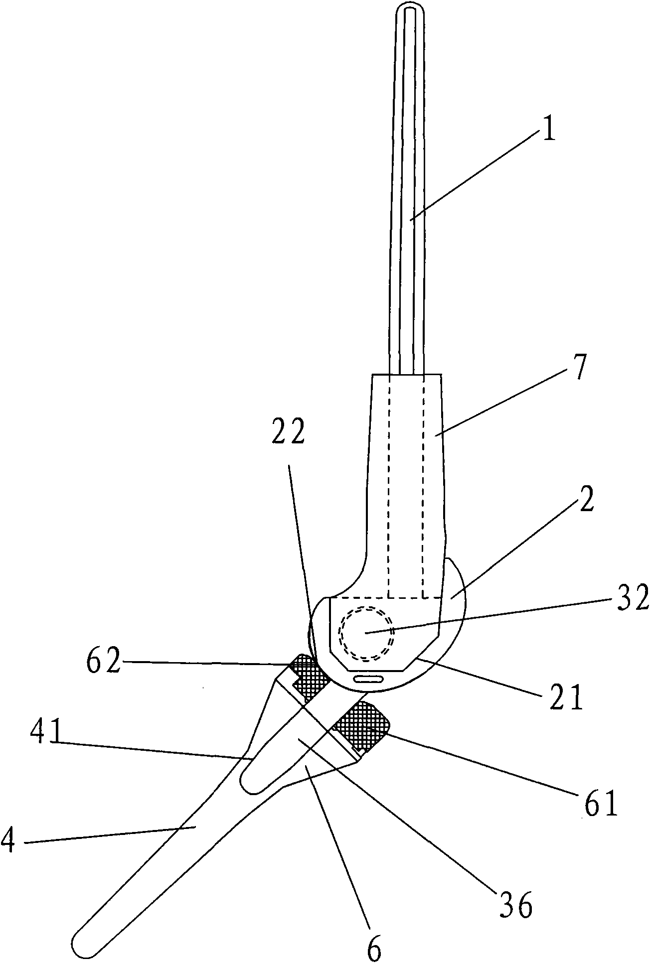
[0027] see figure 2 As shown, the new axial knee prosthesis of the present invention mainly includes a femoral pin 1, a femoral condyle 2, a connector, a tibial pin 4, a tibial plateau 6 and a femoral sleeve 7.

[0028] Wherein, the femoral condyle 2 is provided with a positioning groove 21, and is fixed to the lower part of the femoral needle 1 by inlaying, welding, screwing, etc., or in an integrated structure.

[0029] The tibial plateau 6 is provided with a central hole, and is fixed on the upper part of the tibial medullary pin 4 by means of welding, screwing, or an integral structure, and the tibial plateau 6 contacts and supports the femoral ...


PUM


Abstract

The invention relates to a new axial center type knee joint prosthesis comprising a femur intramedullary pin, a femur condyle, connecting components and a tibia intramedullary pin, also comprsing a tibia platform and a femur sleeve, wherein, the femur condyle is provided with a positioning slot and is fixed at lower part of the femur intramedullary pin; the tibia platform is provided with a centre hole and is fixed at the upper part of the tibia intramedullary pin for holding the femur condyle; the connecting components are T-shaped and comprise a transverse shaft and a vertical shaft, the vertical shaft is inserted into the centre hole of the tibia platform, the transverse shaft is rotatable arranged through the lower part of the femur condyle; the femur sleeve is sleeved at the lower part of the femur intramedullary pin and are butted with the positioning slot of the femur condyle. The new axial center type knee joint prosthesis of the invention can completely recovery the functions of extending and bending, and inward and outward rotating of the knee joint and adopt the bionic molding, the stability is good, the movement requirement of the patient can be satisfied sufficiently under the precondition of protecting limbs, the patient can recovery the movement freely like originally.

Description

technical field [0001] The invention relates to a surgically implanted artificial prosthesis, in particular to a new axial-type knee joint prosthesis. Background technique [0002] The knee joint of the human body has functions such as load bearing and load transfer. It is the largest and most complex joint in the human body. It has the greatest stability when straightened, and considerable flexibility when bent, so as to realize walking, running, Jump and other actions. Commonly used knee prostheses are figure 1 The hinged knee prosthesis shown is composed of a femoral pin 1, a femoral condyle 2, a connector 3, a tibial pin 4 and a fastening screw 5, wherein the connector 3 is a central shaft containing a central shaft pad, The femoral part and the tibial part are connected laterally through the central axis to meet the stability requirements of the joint, and realize the extension and flexion function of the knee joint in a uniaxial manner. [0003] Although the above-m...

Claims


Application Information

Patent Timeline
Patent Type & Authority Applications(China)
IPC IPC(8): A61F2/38
CPCA61F2/38A61F2002/30001
Inventor 张朝锋史春宝
Owner BEIJING CHUNLIZHENGDA MEDICAL INSTR
Why Eureka
Try Eureka