Laser projection system

A laser projection and projection system technology, applied in the field of projection systems, can solve the problems of increasing system complexity and maintenance difficulty, the color gamut of projected images is not wide, and increasing the complexity of installation, etc., to achieve better image effects and vivid colors The effect of brighter colors and improved system reliability

Inactive Publication Date: 2009-11-25
SINOLASER PROJECTION TECH
View PDF1 Cites 7 Cited by
  • Summary
  • Abstract
  • Description
  • Claims
  • Application Information

AI Technical Summary

Problems solved by technology

Although this solves the problem that the picture effect is affected by the speed of the train, the potential safety hazard is large, and the publicity effect is not three-dimensional, but these two projection devices use light bulbs as light sources, which have the following disadvantages: First, they will generate a lot of waste heat and need the help of a good heat dissipation device The heat dissipation and the unsealed optical path cause serious dust ingress and need to be cleaned frequently, which increases the complexity of the system and the difficulty of maintenance, and reduces the reliability of the system. The shock pad increases the complexity of installation; the third is that the life of the bulb is short, generally 5000 hours, and the obvious brightness attenuation can be felt after 3000 hours of actual work
In addition, the color gamut of the projected image of the projector using the light bulb as the light source is not wide, and the color saturation is not high.

Method used


Image

  • Laser projection system
  • Laser projection system
  • Laser projection system

Examples


Embodiment 1

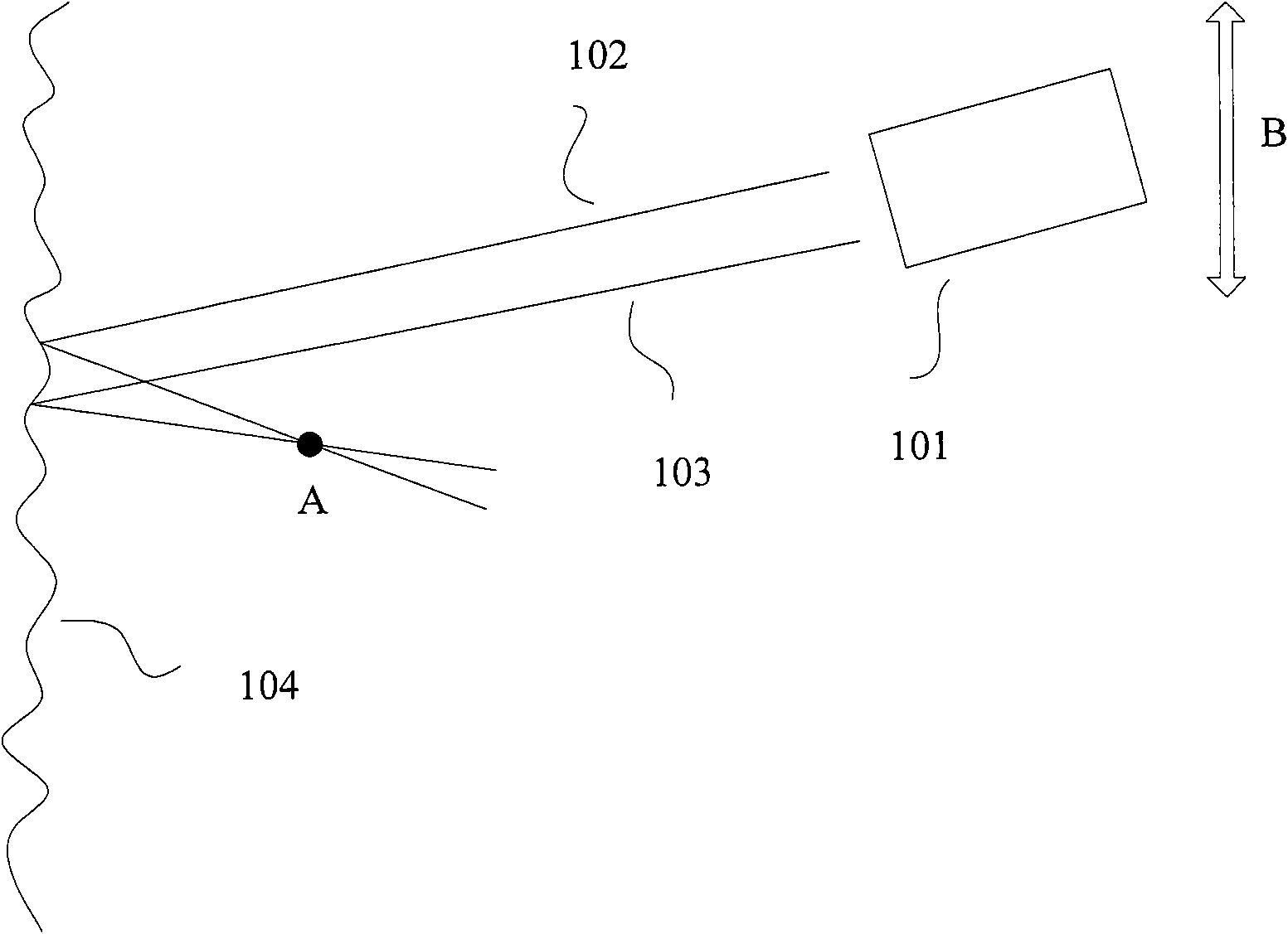
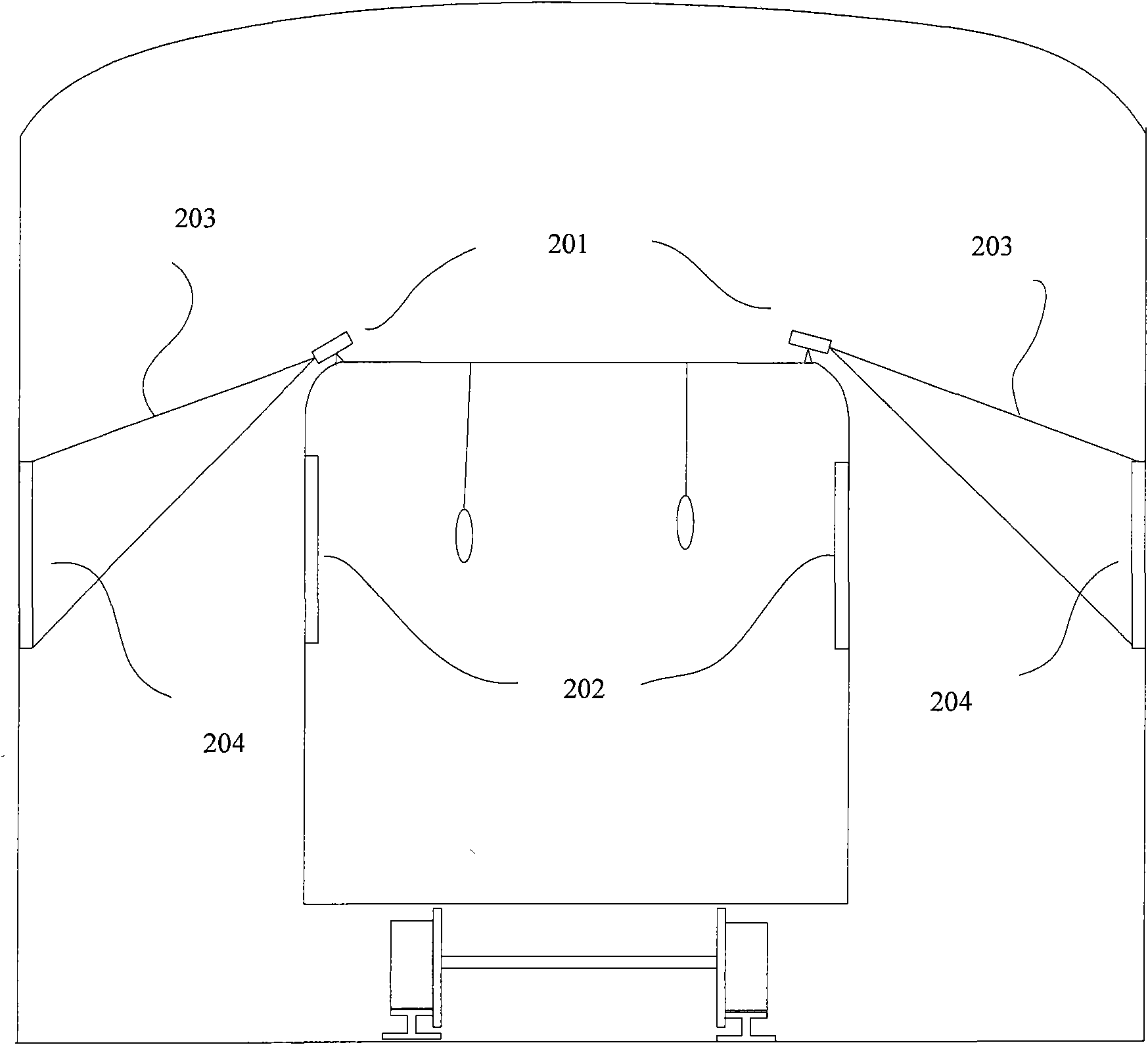
[0036] figure 2 It is a schematic diagram of an embodiment of installing the laser projection device of the present invention on the outside of the top of a subway train. The screen 204 is installed on both sides of the subway track at approximately the same height as the car window 202 and extends along the subway track (the screen 204 can also be directly arranged on the side wall of the subway tunnel). The laser projection device 201 is not provided with a decoherence device. The projected light 203 is projected onto the screen 204 , and the projected content is diffusely reflected by the screen 204 and enters the eyes of passengers through the vehicle window 202 . By installing the laser projection device 201 on the train, the change of the rough surface shape of the screen caused by the movement of the train weakens or even eliminates the speckles generated during the laser projection process (the principle is the same as figure 1 The principle shown in ) is the same), ...

Embodiment 2

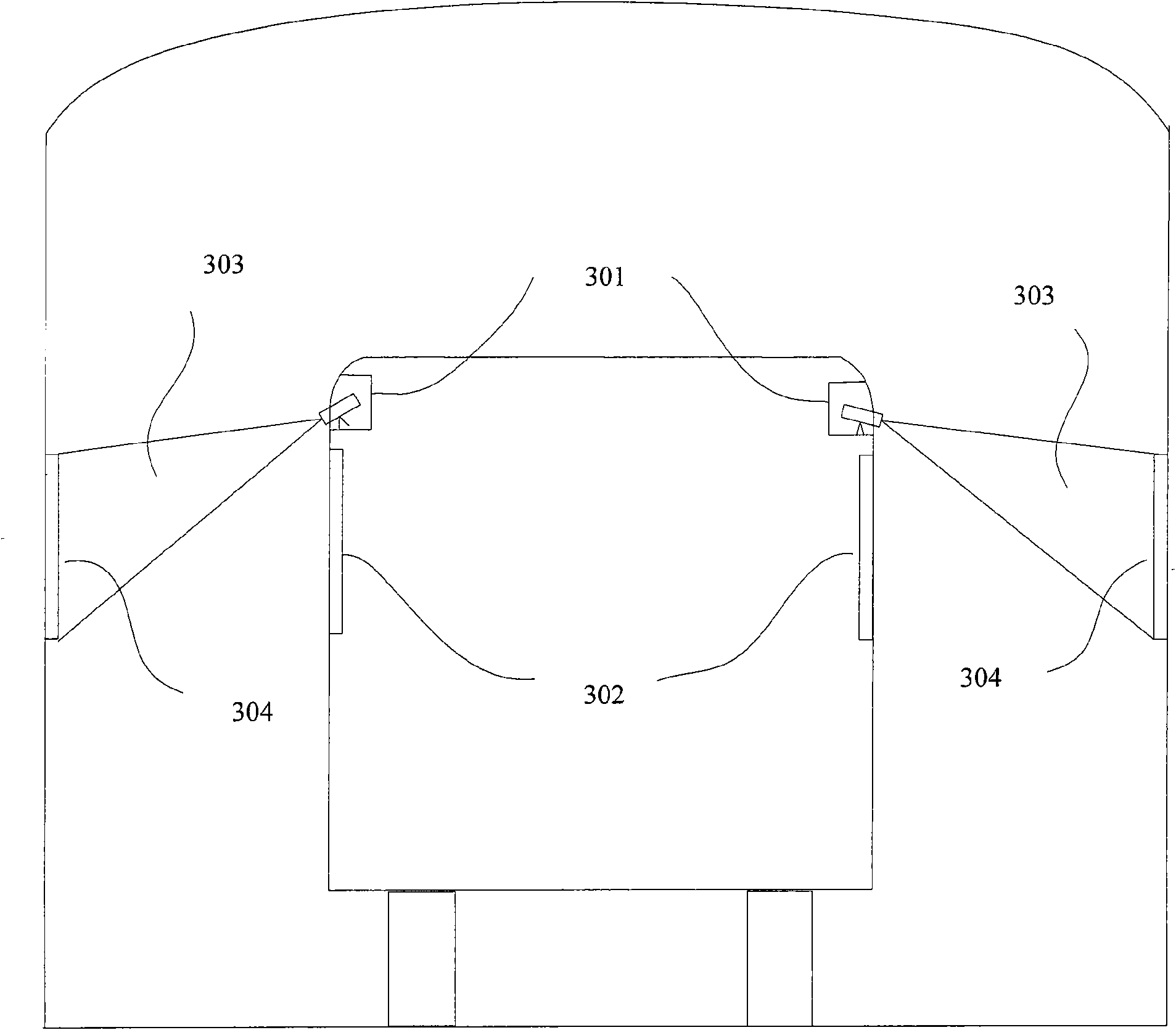
[0039] image 3 It is a schematic diagram of using the projection system of the present invention in a car or a train driving in a tunnel. Wherein the laser projection device is placed on a car or a train, and the tunnel is a mountain tunnel, a river crossing tunnel or an undersea tunnel. The laser projection device 301 is not equipped with a decoherence device, it is placed inside the roof of the vehicle, the lens of the projection device 301 is exposed, and the screen 304 is installed on the side wall of the tunnel at a position substantially equal to the vehicle window 302 and extends along the tunnel ( The screen 304 can also be a painted tunnel side wall), the laser projection device 301 projects the projected light 303 onto the screen 304, and the projected content enters the passenger's eyes through the window 302 after being diffusely reflected by the screen 304. The method described in this embodiment is especially suitable for playing a short video of a tourist attr...


PUM


Abstract

The invention provides a laser projection system, which realizes the decoherence in a laser projection device by using natural movement in an application environment thereof and saves a decohering device used in the prior laser projection system, thereby achieving compact structure and sable performance, improving the utilization rate of laser and reducing system cost. In addition, the laser projection system adopts a laser light source, so the service life of the system is improved greatly and the color range of projected image is wide and the color of the projected images is bright.

Description

technical field [0001] The invention relates to a projection system, in particular to a laser projection system. Background technique [0002] The subway is an indispensable means of transportation in modern cities. Its advantages of safety, punctuality and speed greatly facilitate people's travel. In daily life, in order to effectively use the space on both sides of the subway tunnel to play advertisements and public welfare short films, some people propose to use the principle of film projection to realize dynamic display by using several pictures formed by light boxes or LED screens through animation. The disadvantages of the above method are that there is a limit to the speed of the train; the power consumption is large, which increases the fire hazard in the subway tunnel; the cost is high and it is inconvenient to maintain; there is no synchronous sound to match the display of the picture, and the publicity effect is not three-dimensional. [0003] In response to the ...

Claims


Application Information

Patent Timeline
Patent Type & Authority Applications(China)
IPC IPC(8): G03B21/00G09F19/18G09F19/22
Inventor 许江珂石靖波贾中达
Owner SINOLASER PROJECTION TECH
Why Eureka
Try Eureka