
Power-supply apparatus and control method, power amplifying device

A power supply device and power supply technology, applied in the field of circuits, can solve the problems that switching power supply cannot achieve high bandwidth and high power tracking accuracy at the same time, the switching frequency of switching power supply is difficult, and the overall efficiency of power amplifier is not high, so as to reduce the dynamic error , Improve tracking accuracy and speed, and reduce output power

Active Publication Date: 2009-11-25
HUAWEI DIGITAL POWER TECH CO LTD
View PDF0 Cites 23 Cited by
  • Summary
  • Abstract
  • Description
  • Claims
  • Application Information

AI Technical Summary

Problems solved by technology

However, the existing switching power supply uses an approximate triangular wave to approach the signal to be tracked, and its switching tube is controlled by factors such as process, power, packaging technology and switching loss, and it is difficult to achieve a switching frequency of 10MHz due to both output power and switching speed. above
According to the limiting relationship between the switching frequency and the switching power supply bandwidth (usually the switching power supply bandwidth is less than 1 / 5 of the switching frequency), the switching power supply cannot achieve high bandwidth and high power tracking accuracy at the same time, so the overall efficiency of the prior art power amplifier not tall

Method used


Image

  • Power-supply apparatus and control method, power amplifying device
  • Power-supply apparatus and control method, power amplifying device
  • Power-supply apparatus and control method, power amplifying device

Examples


Embodiment Construction

[0035] The following will clearly and completely describe the technical solutions in the embodiments of the present invention with reference to the accompanying drawings in the embodiments of the present invention. Obviously, the described embodiments are some of the embodiments of the present invention, but not all of them. Based on the embodiments of the present invention, all other embodiments obtained by persons of ordinary skill in the art without creative efforts fall within the protection scope of the present invention.

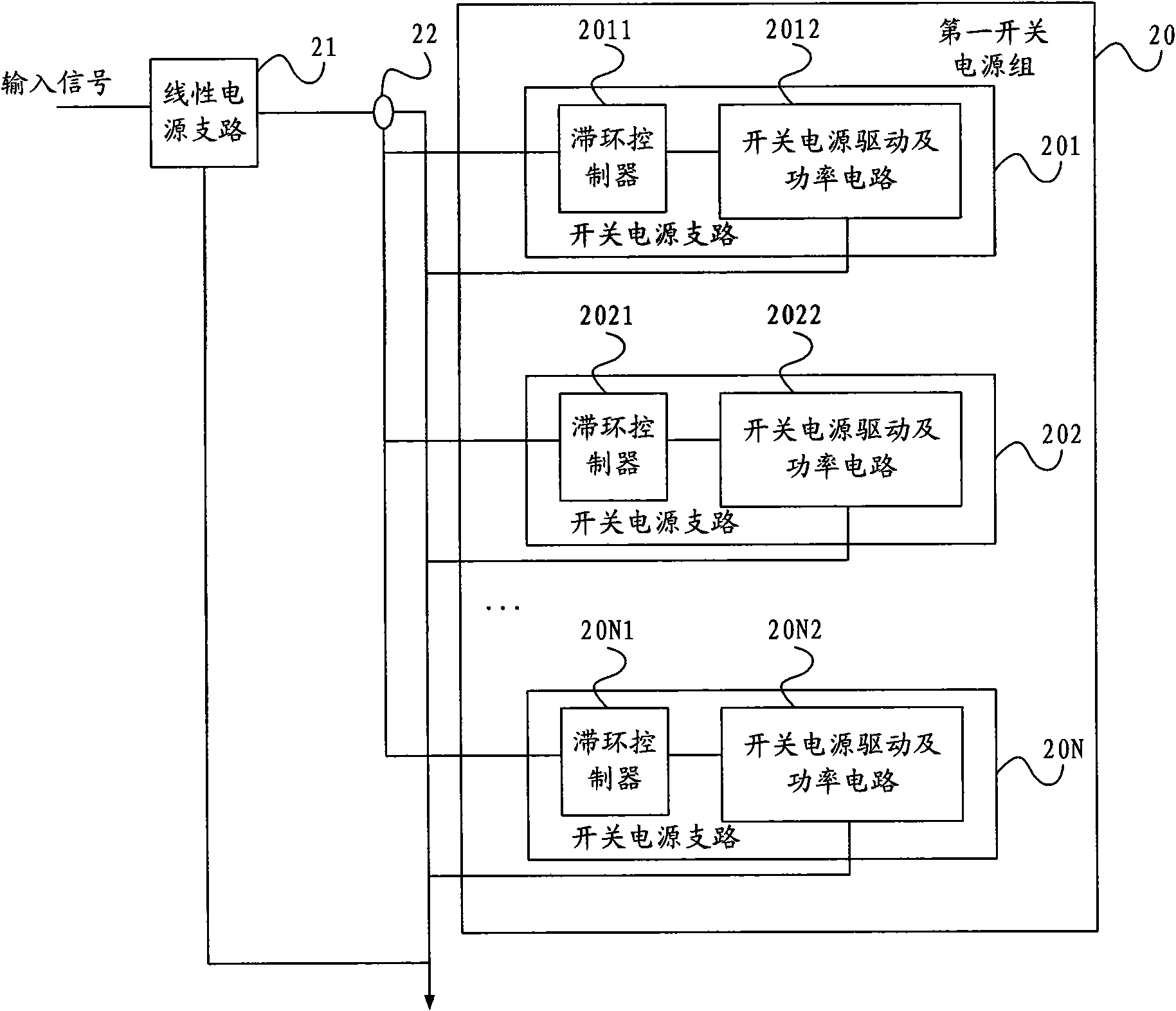
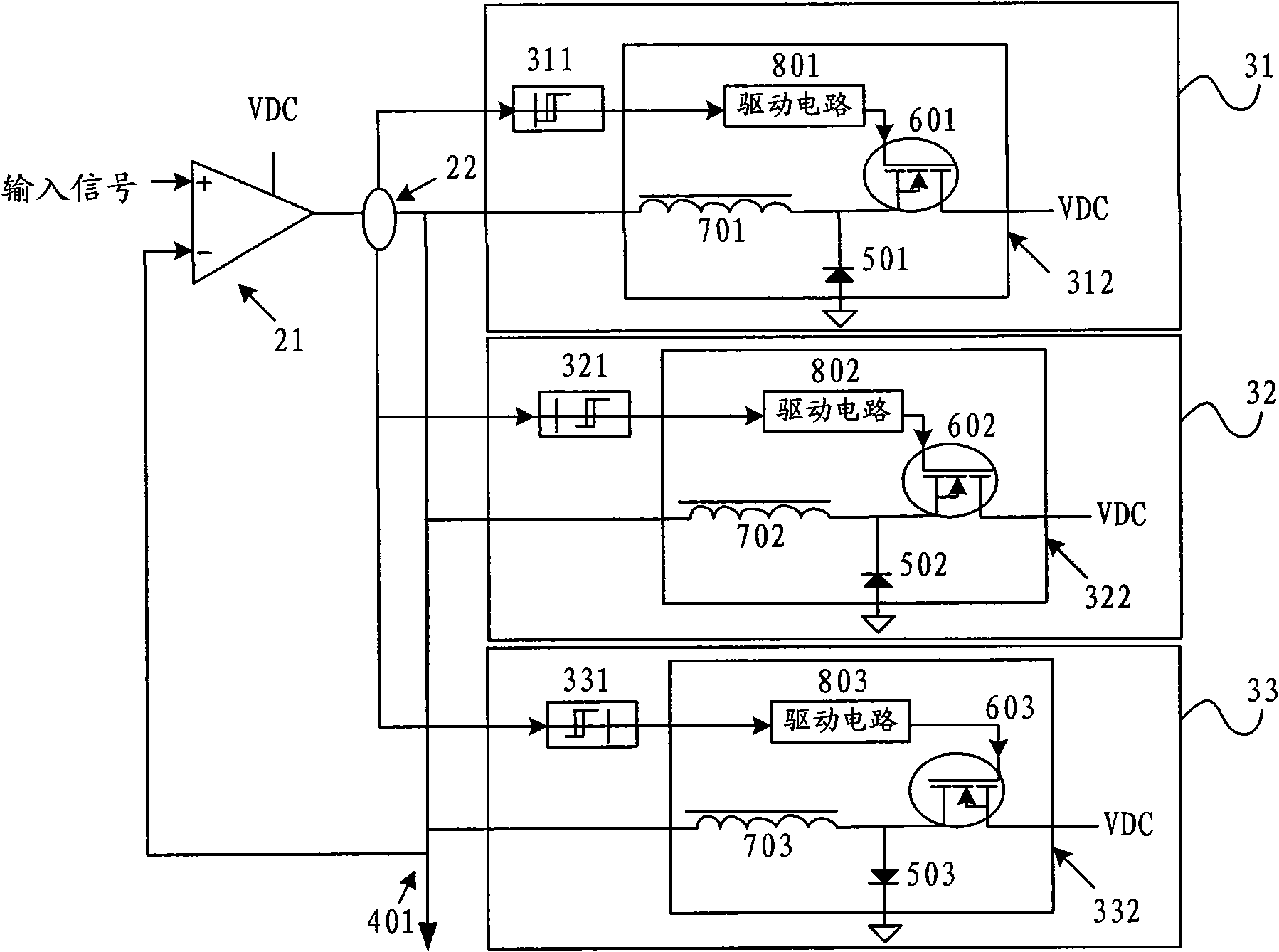
[0036] Such as figure 1As shown, a schematic structural diagram of an embodiment provided for the power supply device of the present invention may include a linear power supply branch 21, a first current detector 22 and a first switching power supply group 20, and the first switching power supply group 20 may include at least Two switching power supply branches: switching power supply branch 201 , switching power supply branch 202 , . . . switching pow...


PUM


Abstract

The embodiment of the invention relates to a power-supply apparatus and control method, a power amplifying device. The device includes a includes linear branch and a first switch power supply group, the first switch power supply group includes a first current detector and at least two switch power supply branches, the switch power supply branch includes a hysteresis controller and a switch power supply drive and power circuit, the input end of the first electrical current detector is connected with the output end of the linear power supply branch, the input end of the hysteresis controller is connected with the output end of the first electrical current detector, the input end of the switch power supply drive and power circuit is connected with the output end of the hysteresis controller, the output end thereof is in parallel connection with the output end of the linear power supply branch. The embodiment of the invention can improve the band width and the tracking accuracy of the switch power supply, further improve the integral efficiency of the ET power amplifier.

Description

technical field [0001] The invention relates to circuit technology, in particular to a power supply device, a control method thereof, and a power amplification device. Background technique [0002] Modern wireless communication systems, such as: Code Division Multiple Address (CDMA for short), Wideband Code Division Multiple Address (WCDMA for short), Universal Mobile Telecommunication System (Universal Mobile Telecommunication System, short for: UMTS), the next generation network (Long Term Evolution, referred to as: LTE) in order to make full use of the spectrum, using the variable envelope modulation technology of amplitude modulation and phase modulation at the same time, this technology has a higher peak-to-average power ratio (Peak-to-Average Power Ratio, referred to as: PAPR) and a wide range of amplitude and frequency dynamic range, but if the PAPR is too high, the transmitting end will have higher requirements on the linearity of the power amplifier, and a linear po...

Claims


Application Information

Patent Timeline
Patent Type & Authority Applications(China)
IPC IPC(8): H02M3/00H02J1/10H03F1/02
Inventor 侯召政唐志
Owner HUAWEI DIGITAL POWER TECH CO LTD
Learn More