Mechanical punch brake device

A braking device, mechanical technology, applied in forging/pressing/hammer devices, forging/pressing/hammering machinery, presses, etc. Easy to heat and other problems, to achieve the effect of saving maintenance costs, low power, easy to heat

Inactive Publication Date: 2009-12-02
SUZHOU FEIYU PRECISION TECH
View PDF5 Cites 2 Cited by
  • Summary
  • Abstract
  • Description
  • Claims
  • Application Information

AI Technical Summary

Problems solved by technology

Therefore, when the machine tool works for a long time, due to the frequent operation of the solenoid valve 6, the solenoid valve 6 is very likely to generate heat and burn out the coil, which shortens the life of the solenoid valve 6, which not only affects normal production, but also increases maintenance costs.
In addition, since the electromagnetic force of the electromagnetic valve 6 needs to be greater than the spring force, the electromagnetic brake device has high power and consumes a lot of energy.

Method used


Image

  • Mechanical punch brake device
  • Mechanical punch brake device
  • Mechanical punch brake device

Examples


Embodiment Construction

[0013] The present invention will be described in detail below in conjunction with the accompanying drawings.

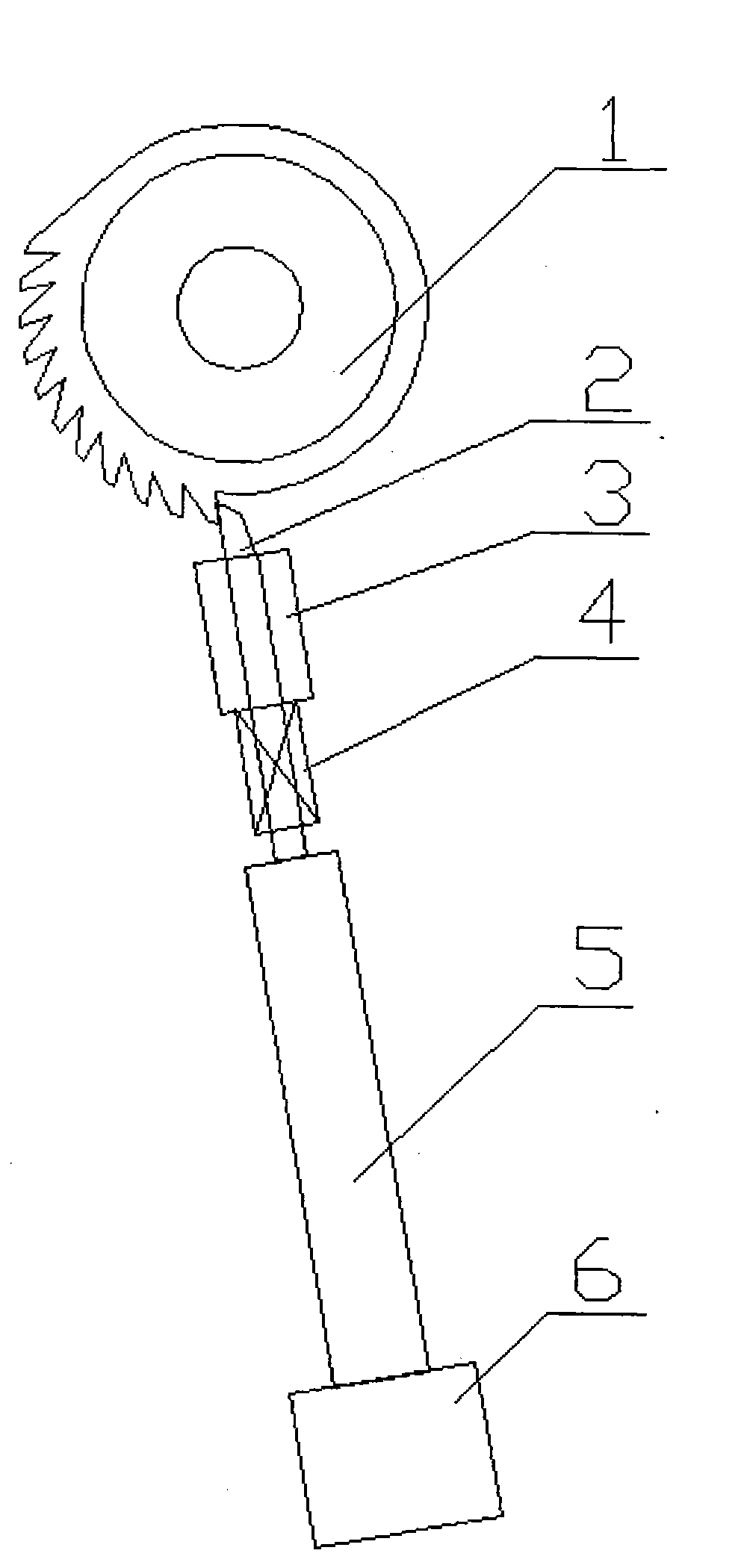
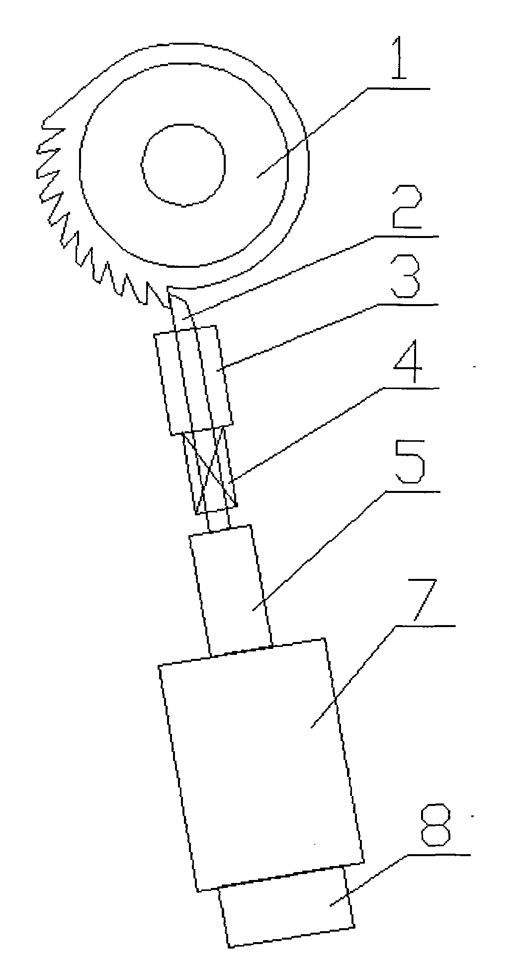
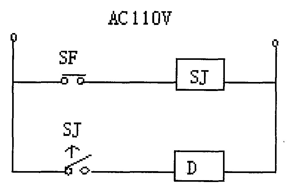
[0014] figure 2 It is a structural schematic diagram of the mechanical braking device in the present invention; image 3 It is the electrical principle diagram of the electromagnetic induction device of the present invention.

[0015] As shown in the figure, the mechanical brake device of the present invention includes a ratchet 1, a brake block 2, a spring 4, a brake block guide 3, a connecting rod 5, a cylinder 7, and an electromagnetic induction device 8. The ratchet 1 cooperates with the brake block 2 to brake The end of the block 2 is inserted into the teeth of the ratchet 1, preventing the rotation of the ratchet 1. The brake shoe guiding device 3 is sleeved on the brake shoe 2, and is fixed on the punch press, and plays a guiding role in the movement of the brake shoe 2. The other end of brake shoe 2 is connected with pull rod 5, is driven by pull rod 5. ...


PUM


Abstract

The invention relates to a mechanical punch brake device, which comprises a ratchet wheel, a brake block, a spring, a brake block guide device and a pull rod, wherein the ratchet wheel is matched with the brake block which is connected with the pull rod; the brake block guide device is sleeved on the brake block and fixed on a punch; and the spring is sleeved on the brake block, one end of the spring acts on the brake block, while the other end acts on the punch. The mechanical punch brake device is characterized in that: the mechanical punch brake device also comprises a cylinder; the pull rod is connected with a piston rod of the cylinder; the air path of the cylinder is provided with an electromagnetic induction device for controlling the action of the cylinder; and the punch is provided with a switch which is electrically connected with the electromagnetic induction device. The mechanical punch brake device opens the air path by means of the magnetic force generated by an electromagnetic valve to make the cylinder work. The cylinder force is utilized to overcome the spring force to realize the work of sliding blocks on a machine tool, so the power and the energy consumption of the electromagnetic valve arranged on the cylinder are small to greatly prolong the service life and save maintenance expenses of enterprises.

Description

technical field [0001] The invention relates to a punching machine, in particular to a mechanical punching machine braking device used for a mechanical forging machine tool to replace the original electromagnetic braking device, and belongs to the technical field of mechanical processing. Background technique [0002] At present, the brake device of mechanical forging machine tools generally adopts electromagnetic brake device in the market. figure 1 It is a schematic diagram of the structure of the brake device in the prior art. After the machine tool is started, the flywheel rotates, the brake device is in the working state, and the upper slider does not work. When the operation button is pressed, the solenoid valve 6 is energized to generate a magnetic field, and the pull rod 5 is pulled by magnetic force. Brake shoe 2 disengages. The upper slide block of the machine tool starts to work, and when the upper slide block completes one stroke and goes up to the highest point...

Claims


Application Information

Patent Timeline
Patent Type & Authority Applications(China)
IPC IPC(8): B30B15/10B21J13/00
Inventor 杨俭华张全明
Owner SUZHOU FEIYU PRECISION TECH
Why Eureka
Try Eureka