Hydraulic decompression device of engine camshaft

A decompression device, camshaft technology, applied in the direction of engine components, machines/engines, valve devices, etc., can solve the problems of stop lag, stop resistance reduction, exhaust valve can not be completely closed, etc., to achieve smooth start, start resistance Reduced effect

Inactive Publication Date: 2009-12-02
LONCIN MOTOR
View PDF0 Cites 0 Cited by
  • Summary
  • Abstract
  • Description
  • Claims
  • Application Information

AI Technical Summary

Problems solved by technology

The centrifugal force increases from small to large during the starting process of the engine. When the centrifugal force reaches the point where the centrifugal block can move centrifugally, the centrifugal block breaks away from the control of the decompression body. Enter normal work; the centrifugal force changes from large to small during the shutdown process of the engine. Once the centrifugal force is smaller than the centrifugal block and cannot form centrifugal motion, the centrifugal block will return immediately under the action of the spring to push the decompression body into the decompression working state, thereby making the exhaust The valve cannot be completely closed, and part of the gas in the cylinder is discharged, resulting in a decrease in the amount of compressed gas in the cylinder, and a decrease in the compression resistance in t

Method used


Image

  • Hydraulic decompression device of engine camshaft
  • Hydraulic decompression device of engine camshaft

Examples


Embodiment Construction

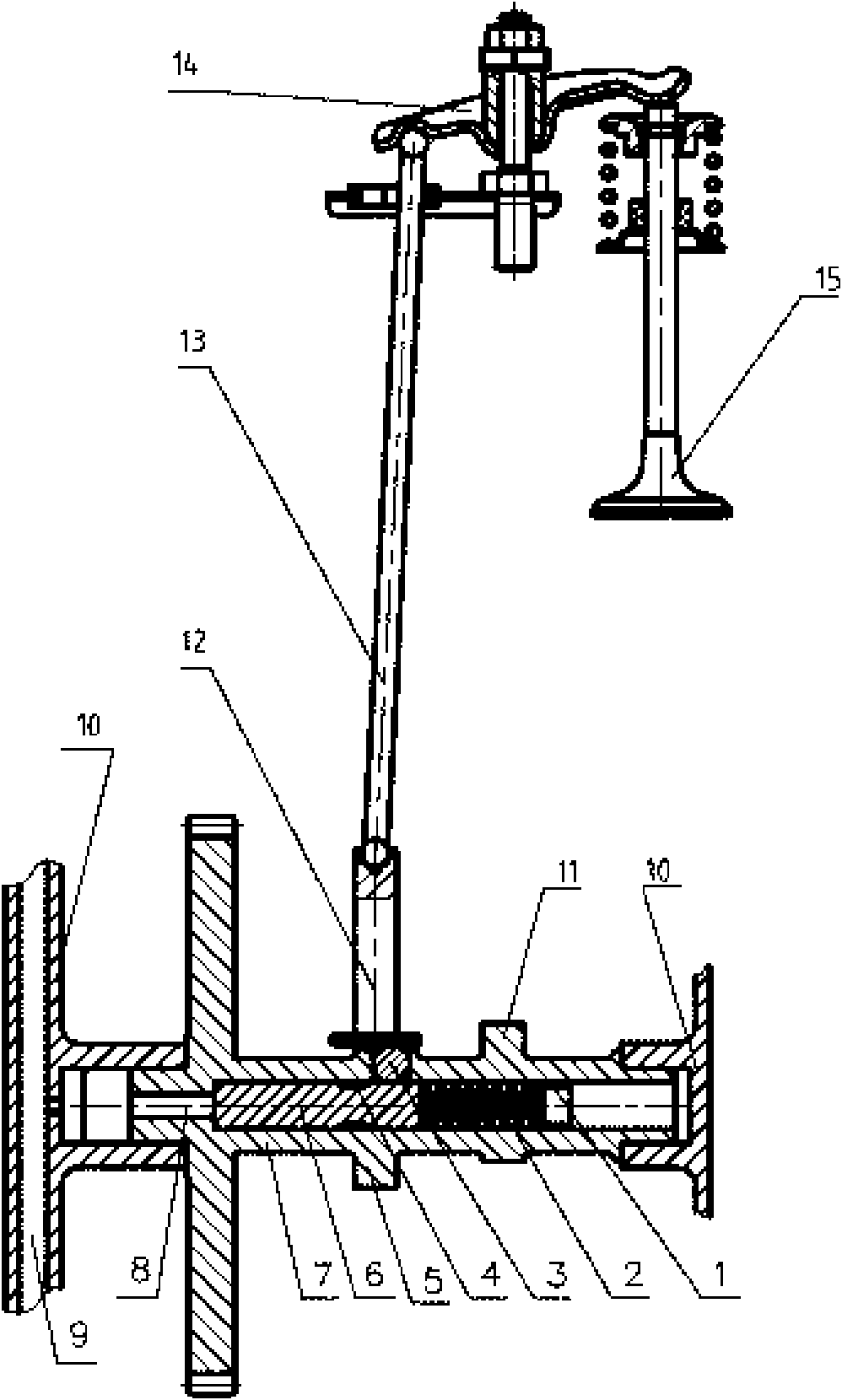
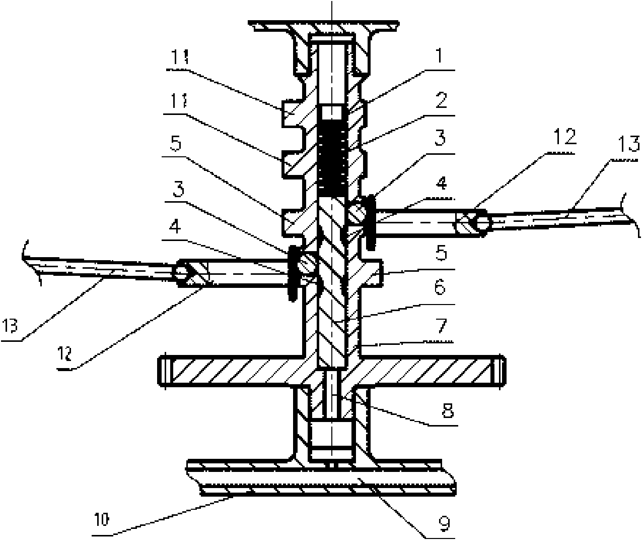
[0016] see figure 1 , is an embodiment arranged on the lower camshaft of the engine. The engine camshaft hydraulic decompression device includes a camshaft 7 provided with an intake cam 11 and an exhaust cam 5 , and the two ends of the camshaft are rotatably supported on the casing 10 . The axial direction of the camshaft 7 is provided with a stepped shaft center hole, the small diameter section of the stepped shaft center hole is a throttle hole 8 communicating with the lubricating oil passage 9 provided on the box body 10, and the exhaust cam 5 is close to the stop stroke base circle In the radial direction, there is a hole for placing the decompression body connected to the large-diameter section of the axial hole. The hole for placing the decompression body is provided with a limit flange at the end of the exhaust cam near the base circle of the stop stroke. A movable decompression body 3 is set in the hole where the decompression body is placed. The decompression body 3 ...


PUM

PropertyMeasurementUnit
Slopeaaaaaaaaaa

Abstract

The invention discloses a hydraulic decompression device of an engine camshaft. The camshaft is provided with a ladder-shaped axis hole in the axial direction; the small diameter section of the axis hole is a throttling hole; a basic circle of the shortest stopping distance close to an exhaust cam is radially provided with a hole which is used for accommodating a decompression body and communicated with a large diameter section of the axis hole; the inside of the hole for accommodating the decompression body is provided with a movable decompression body; a mandrel is in sliding fit with the large diameter section of the axis hole and jacks up the decompression body to allow one end of the decompression body to be higher than the end face of a hole mouth by 0.5 to 1.5 mm; one end of the mandrel is limited by a hole shoulder of the ladder-shaped axis hole; the other end of the mandrel is supported against a compression spring assembled in the axis hole; the compression spring is positioned by a plug fixed inside the axis hole; and the mandrel is provided with a groove which allows the decompression body to fall off after being moved. The hydraulic decompression device utilizes the pressure of engine lubricating oil to retard the decompression body to enter a decompression working state, keeps resistance of a cylinder and shortens the stop time when an engine is at a low rotational speed.

Description

technical field [0001] The invention relates to a decompression device for an engine camshaft, in particular to a hydraulic decompression device for an engine camshaft of a general gasoline engine. Background technique [0002] The engine start-up decompression mechanism of the existing general-purpose gasoline engine is usually a centrifugal decompression device arranged on the camshaft. When the engine is stopped, there is no centrifugal force. The valve is not closed tightly, and the pressure in the cylinder is reduced, so as to reduce the starting resistance, and the engine can be started smoothly when the engine starts. For the control of the decompression body, the decompression body releases the restriction on the rocker arm of the exhaust valve, so that the exhaust valve can be completely closed and the engine can work normally. If the engine has an electric start structure, the starter motor can be made smaller, and the matching battery is also smaller, which impro...

Claims


Application Information

Patent Timeline
IPC IPC(8): F01L13/08
Inventor 张永就李炼
Owner LONCIN MOTOR
Why Eureka
Try Eureka