Exposure equipment focal distance monitoring method

A technology of equipment and focal length, applied in the direction of microlithography exposure equipment, photolithography exposure equipment, etc., can solve the problems of low efficiency, complicated and cumbersome steps, etc., and achieve the effect of simple process steps and high measurement efficiency

Inactive Publication Date: 2009-12-02
SEMICONDUCTOR MANUFACTURING INTERNATIONAL (BEIJING) CORP
View PDF1 Cites 25 Cited by
  • Summary
  • Abstract
  • Description
  • Claims
  • Application Information

AI Technical Summary

Problems solved by technology

[0007] The invention provides a method for monitoring the focal length of exposure equipment t

Method used


Image

  • Exposure equipment focal distance monitoring method
  • Exposure equipment focal distance monitoring method
  • Exposure equipment focal distance monitoring method

Examples


Embodiment Construction

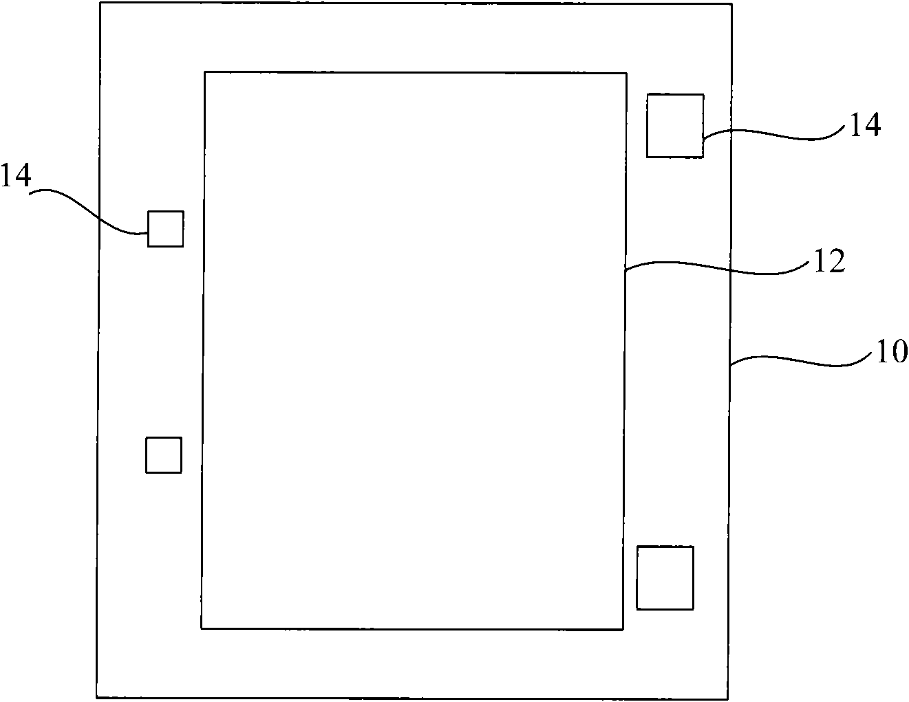
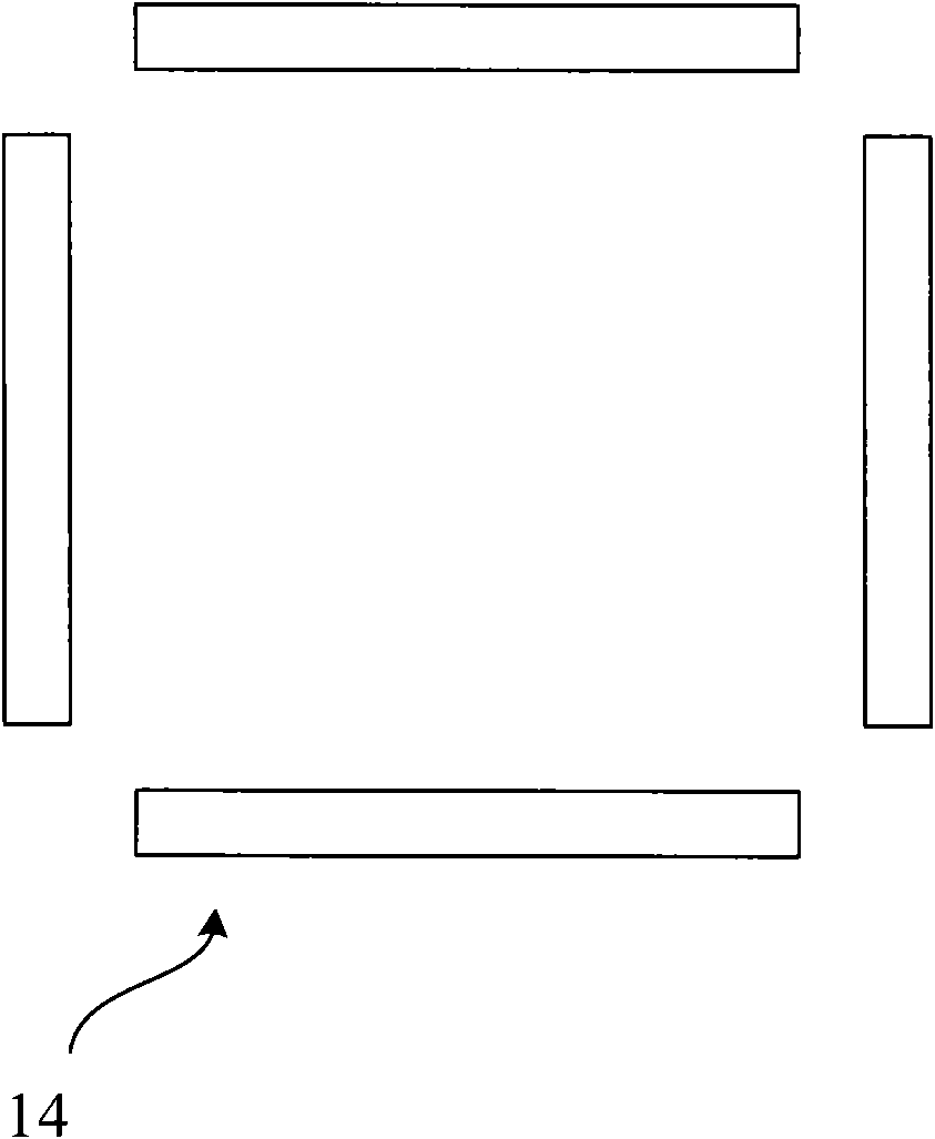
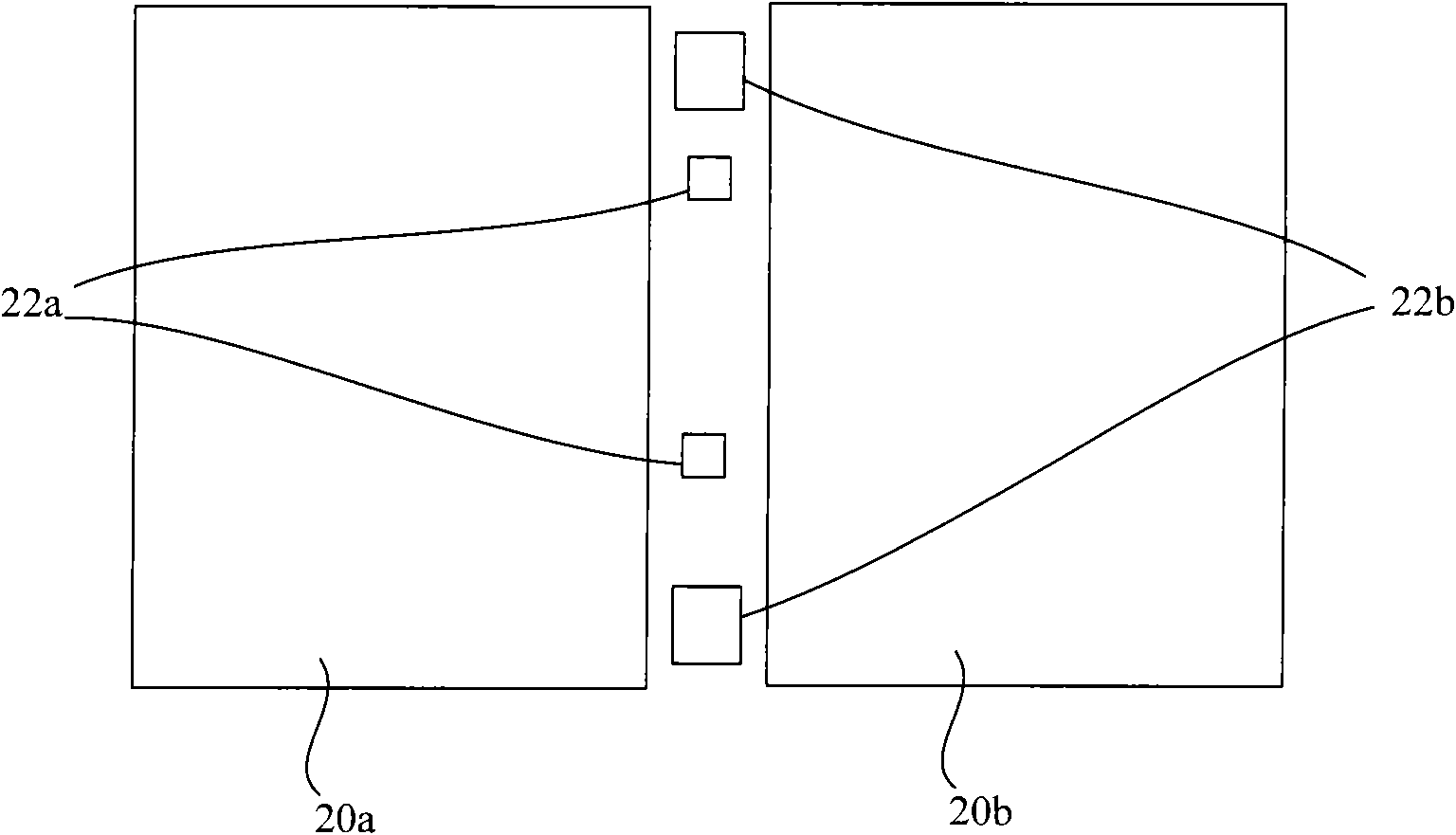
[0028] The specific embodiments of the present invention will be described in detail below in conjunction with the accompanying drawings.

[0029] In the following description, numerous specific details are set forth in order to provide a thorough understanding of the present invention. However, the present invention can be implemented in many other ways different from those described here, and those skilled in the art can make similar extensions without violating the connotation of the present invention, so the present invention is not limited by the specific implementations disclosed below.

[0030] Secondly, the present invention is described in detail using schematic diagrams. When describing the embodiments of the present invention in detail, for the convenience of explanation, the cross-sectional view showing the device structure will not be partially enlarged according to the general scale, and the schematic diagram is only an example, and it should not be limited here. ...


PUM


Abstract

An exposure equipment focal distance monitoring method comprises the following steps: providing a maskplate with a benchmark tag, transferring the benchmark tag onto a substrate by photoetching technique and etching technique to form a benchmark tag pattern on the substrate; providing a maskplate with a test tag; forming a photoetching adhesive layer on the substrate with the benchmark tag pattern, and transferring the test tag onto the photoetching adhesive layer by using the exposure equipment to execute the photoetching technique to form a test tag pattern; measuring offset of the test tag pattern and the benchmark tag pattern; and if the offset is not equal to the target value, judging that the exposure equipment offsets from the optimal exposure position. The method is simple in technique steps and high in measurement efficiency.

Description

technical field [0001] The invention relates to the technical field of semiconductor manufacturing, in particular to a method for monitoring the focal length of an exposure device. Background technique [0002] In the manufacturing process of semiconductor integrated circuits, the layout pattern on the mask plate is transferred to the photoresist layer of the semiconductor substrate through the exposure equipment (ExposureEquipment) of the photolithography process to form a photoresist pattern; then, with the photoresist pattern As a mask layer, a subsequent etching or ion implantation process is performed on the semiconductor substrate. [0003] In the photolithography process, the line width of the photoresist pattern and its sidewall profile will be affected by the focus of the exposure equipment. The line width and profile of the photoresist pattern will directly affect the subsequent etching or ion implantation process, therefore, the monitoring of the focus status of ...

Claims


Application Information

Patent Timeline
IPC IPC(8): G03F7/20
Inventor 肖楠
Owner SEMICONDUCTOR MANUFACTURING INTERNATIONAL (BEIJING) CORP
Why Eureka
Try Eureka