
Grid and formation method thereof

A gate and polysilicon layer technology, applied in the direction of electrical components, circuits, semiconductor devices, etc., can solve the problems of increased series resistance, difficulty in forming shallow junctions, limited Emax effect, etc., to expand the overlapping area and improve heat load The effect of flow particle effect

Inactive Publication Date: 2009-12-02
SEMICONDUCTOR MANUFACTURING INTERNATIONAL (BEIJING) CORP
View PDF1 Cites 9 Cited by
  • Summary
  • Abstract
  • Description
  • Claims
  • Application Information

AI Technical Summary

Problems solved by technology

[0005] However, when applying the above-mentioned traditional methods to improve the hot carrier effect, there are more or less disadvantages
For example, when phosphorus-doped drain region is selected, in order to make the resistance of source and drain relatively small, the dose of phosphorus implanted must be above 1E15, so the Isub of the device is an order of magnitude smaller than that of arsenic implanted; when double-diffused drain region is selected, it is difficult A shallow junction is formed, so the effect on reducing Emax is limited; when the method of improving the lightly doped drain region is selected, due to the introduction of the n-region, the LDD structure will also increase the series resistance, resulting in a decrease in the driving current; resulting in LDD's The process parameters must be carefully optimized to obtain the best device performance; when choosing the method of reducing the supply voltage, considering the compatibility issue, the voltage cannot be completely reduced synchronously with the reduction of the line width, which makes the hot carrier effect limited improvement

Method used


Image

  • Grid and formation method thereof
  • Grid and formation method thereof
  • Grid and formation method thereof

Examples


Embodiment Construction

[0021] Although the invention will be described in more detail below with reference to the accompanying drawings, in which preferred embodiments of the invention are shown, it should be understood that those skilled in the art can modify the invention described herein and still achieve the advantageous effects of the invention. Therefore, the following description should be understood as a broad instruction for those skilled in the art, rather than as a limitation of the present invention.

[0022] In the interest of clarity, not all features of an actual implementation are described. In the following description, well-known functions and constructions are not described in detail since they would obscure the invention with unnecessary detail. It should be appreciated that in the development of any actual embodiment, numerous implementation details must be worked out to achieve the developer's specific goals, such as changing from one embodiment to another in accordance with sy...


PUM


Abstract

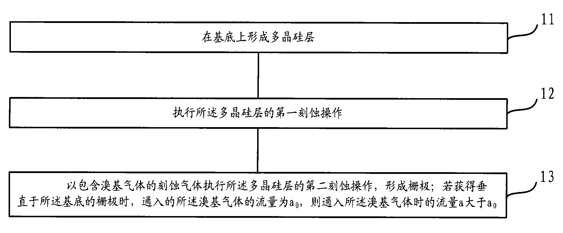
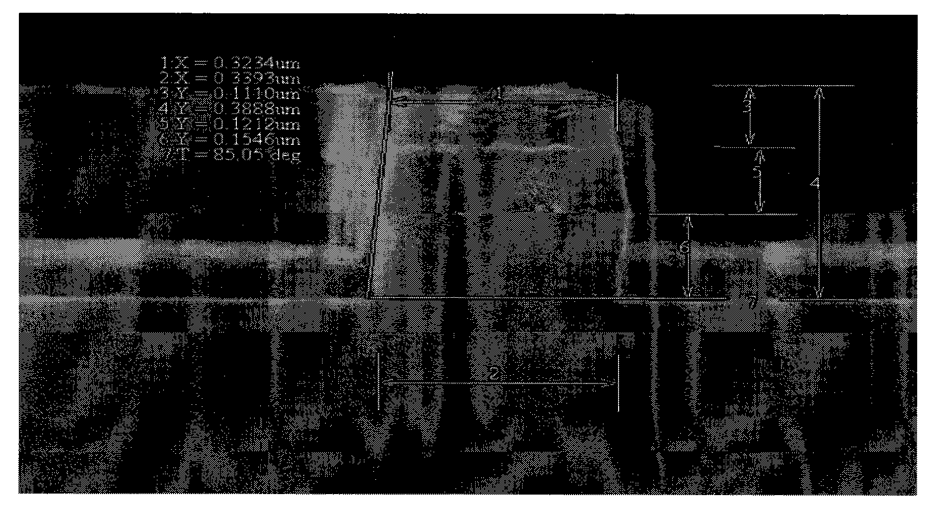
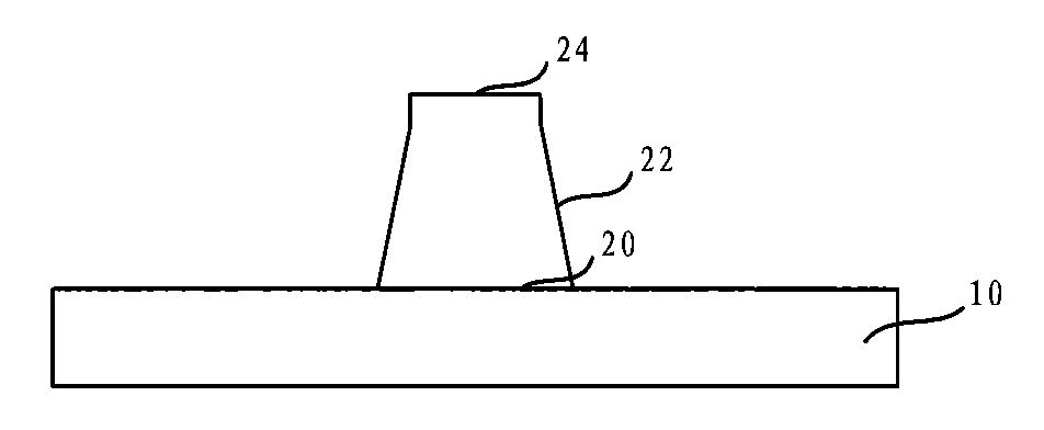
A grid formation method comprises the following steps: forming a polysilicon layer on a substrate; executing first etching operation on the polysilicon layer and executing second etching operation on the polysilicon layer by etching gases containing bromine-based gases to form the grid; if the flow of the pumped bromine-based gases is a0 when the grid perpendicular to the substrate is obtained, the flow a when the bromine-based gases are pumped is more than a0. A grid is formed on the substrate and comprises the polysilicon layer; wherein, the polysilicon layer comprises a top wall, a bottom wall opposite to the top wall and a side wall jointed with the top wall after extending upwards from the edge of the bottom wall; the included angle of at least partial side wall and the bottom wall is less than 90 degrees. Under the condition of keeping the electrical length of a channel unchanged, the overlapped region of the grid and a drain is expanded and the hot carrier effect is improved.

Description

technical field [0001] The invention relates to the technical field of semiconductor manufacturing, in particular to a gate and a forming method thereof. Background technique [0002] In the semiconductor manufacturing process, increasing demands continue to push the semiconductor manufacturing process towards the direction of high integration and low power consumption. However, as the size of the chip decreases, the power supply voltage and operating voltage of the chip do not decrease a lot accordingly, so the corresponding electric field strength increases, resulting in an increase in the movement rate of electrons. When high-energy electrons collide with the crystal lattice, the lattice atoms will be ionized to generate electron and hole pairs. Part of the electrons can change the direction of motion due to scattering, and can overcome the barrier of the oxide layer and enter the gate oxide layer, resulting in a device The electrical parameters degenerate, this effect i...

Claims


Application Information

Patent Timeline
IPC IPC(8): H01L29/423H01L29/78H01L21/28H01L21/3065H01L21/336
Inventor 吴永坚甘正浩廖金昌
Owner SEMICONDUCTOR MANUFACTURING INTERNATIONAL (BEIJING) CORP
Learn More