Rotary printing press and method for adjusting a cylinder thereof

A technology for printing presses and adjustment systems, applied in the field of roller adjustment, which can solve problems such as long time

Active Publication Date: 2009-12-02
BOBST BIELEFELD
View PDF1 Cites 12 Cited by
  • Summary
  • Abstract
  • Description
  • Claims
  • Application Information

AI Technical Summary

Problems solved by technology

Still, the adjustment process takes a conside

Method used


Image

  • Rotary printing press and method for adjusting a cylinder thereof
  • Rotary printing press and method for adjusting a cylinder thereof
  • Rotary printing press and method for adjusting a cylinder thereof

Examples


Embodiment Construction

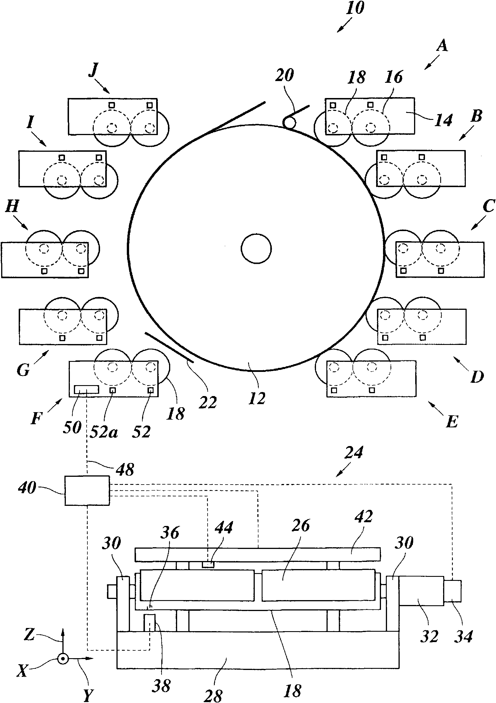
[0066] As an example of a printing machine to which the present invention can be applied, figure 1 A known flexographic printing press is shown comprising a central impression cylinder (CI) 12 and ten inking stations A-J arranged around the periphery of the CI. Each inking station has a frame 14 in which an embossing roller 16 and a plate cylinder 18 are rotatably and adjustably supported. As is well known, the embossing roll is inked by means of an inking system and / or a chamber doctor blade (not shown) and can be pressed onto the plate cylinder 18 so that the ink is transferred to the plate cylinder 18 bearing the printed image. of the perimeter.

[0067] A continuous printing web 20 moves around the periphery of the CI 12, thus passing each inking station A-J as the CI rotates.

[0068] exist figure 1 Inking stations A-E are shown in working condition. In this state, the embossing roller 16 and the plate cylinder 18 are driven and rotated at a speed equal to the periphe...


PUM


Abstract

The invention relates to a rotary printing press comprising a number of colour decks (A-J), at least one of which comprises a cylinder (16, 18), and an adjusting system for adjusting the position of the cylinder (16, 18) in relation to at least one other component (12) of said printing press. Said rotary printing press is characterised in that the at least one colour deck (F) comprises a control unit (50) that is configured to capture and process data relating to the cylinder, said data describing the topography of the surface of said specific cylinder and/or a spatial relationship between a printing pattern and a reference mark (36) embodied on the cylinder. The control unit (50) is configured such that the adjusting system can be controlled according to said adjusting data in order to optimally adjust the position of the cylinder for printing, producing little or no waste at all.

Description

technical field [0001] The invention relates to a method for adjusting rollers in a rotary printing press. Background technique [0002] The roller to be adjusted can be, for example, a printing cylinder or a printing cylinder sleeve (sleeve) in a flexographic printing press, a gravure printing press or an offset printing press, or an embossing roller in a flexographic printing press. The parameter that must be adjusted for such a roller can be the force or pressure with which the peripheral surface of the roller is pressed radially against another part of the printing press. For example, if the roll to be adjusted is a plate cylinder, the circumference of the roll is pressed radially onto the impression cylinder with the stated force or pressure, or if the roll to be adjusted is an embossing roll, the circumference of the roll is pressed with said force or pressure The force or pressure is applied radially onto the plate cylinder. This pressure parameter can be defined se...

Claims


Application Information

Patent Timeline
IPC IPC(8): B41F5/18B41F5/24B41F13/14B41F33/00G01B11/24B41F5/20B41F7/18B41F9/04B41F13/02B41F13/12B41F13/34B41F13/38B41F31/30B41C1/10
CPCB41F13/14B41P2200/12B41P2227/30B41F13/30B41F3/56B41F9/02
Inventor 戈登·怀特洛格奥尔格·格劳托夫安德烈亚斯·屈克尔曼
Owner BOBST BIELEFELD
Why Eureka
Try Eureka