Mainshaft transmission system of numerically-controlled precise grinding polisher
A spindle drive and polishing machine technology, which is applied to the parts of grinding machine tools, grinding/polishing equipment, grinding drive devices, etc., can solve the problems of high requirements for use conditions, poor anti-interference ability, slow dynamic response, etc., to achieve The effect of low maintenance and maintenance requirements, strong anti-interference ability and fast response speed
- Summary
- Abstract
- Description
- Claims
- Application Information
AI Technical Summary
Problems solved by technology
Method used
Image
Examples
Embodiment 1
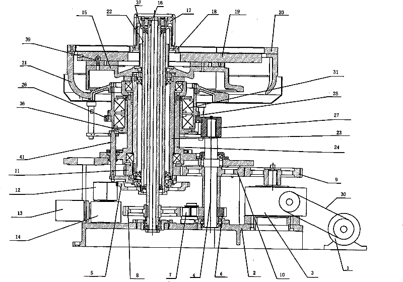
[0027] Example 1, see figure 1 , 5 , the spindle drive system of the CNC precision grinding and polishing machine includes a main motor 1 and a main support 2 arranged on the frame, and the main motor 1 is connected with the main reduction box 3 on the main support 2 through a belt 30 It is connected, and its characteristic is that: the support sleeve 24 is installed on the main support 2, the lifting sleeve 36 is arranged on the outside of the support sleeve 24, and the lower part of the lifting sleeve 36 is provided with a lifting mechanism 41; On the cover 36, the ring gear cover 25 is provided with the ring gear driven gear 26, the ring gear support 21 is fixedly installed on the upper part of the ring gear cover 25, the ring gear 20 is set on the ring gear support 21, and the support sleeve 24 is equipped with the lower gear through the bearing. Disc shaft 23, the upper part of the lower disc shaft 23 is fixedly equipped with a tray 15, and the lower disc 19 is arranged...
Embodiment 2
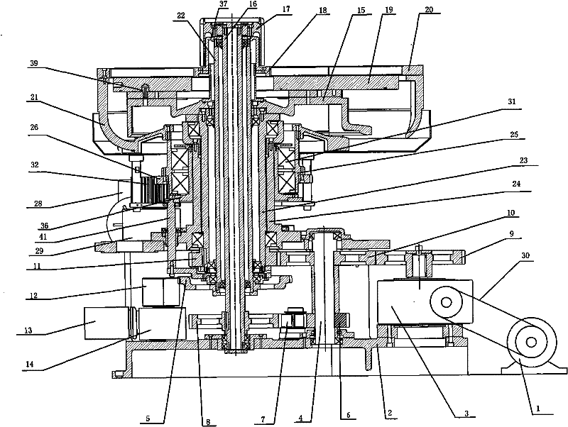
[0031] Example 2, see figure 2 , the difference from embodiment 1 is that the power output shaft of the main reduction box 3 on the main support 2 is provided with a power input gear 9, the power input gear 9 is meshed with the lower disk driving gear 10, and the lower disk driving gear 10 meshes with the driven gear 11 of the lower plate; the driving gear 10 of the lower plate is set on the power transmission shaft 4, the power transmission shaft 4 is set on the main support 2 through the bearing, and the lower end of the power transmission shaft 4 is provided with the upper plate driving gear 6 , The upper plate driving gear 6 meshes with the first idler gear 7 located on the main support 2, and the first idler gear 7 meshes with the upper plate driven gear 8. The main support 2 is also provided with a sun gear motor 13 and a ring gear motor 28, the sun gear motor 13 is connected with the sun gear reduction box 14, and the power output shaft of the sun gear reduction box 14...
Embodiment 3
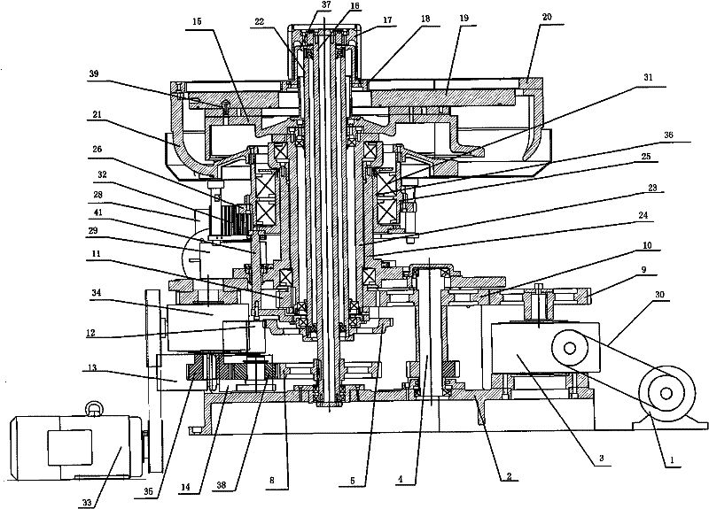
[0032] Example 3, see image 3 , different from Embodiment 1 is that the frame is also provided with an upper plate motor 33, the upper plate motor 33 is connected with the upper plate reduction box 34 by a belt, and the power output shaft of the upper plate reduction box 34 is provided with an upper plate Driving gear 35, the upper disk driving gear 35 meshes with the second idler gear 38, the second idler gear 38 meshes with the upper disk driven gear 8, and the power output shaft of the main reduction box 3 on the main support 2 The power input gear 9 is arranged on the top, and the power input gear 9 meshes with the lower disk driving gear 10, and the lower disk driving gear 10 meshes with the lower disk driven gear 11; the lower disk driving gear 10 is arranged on the power transmission shaft 4, and the power Transmission shaft 4 is located on the main support 2 through bearings. The main support 2 is also provided with a sun gear motor 13 and a ring gear motor 28, the s...
PUM
 Abstract
Description
Claims
Application Information
 - R&D
- Intellectual Property
- Life Sciences
- Materials
- Tech Scout
- Unparalleled Data Quality
- Higher Quality Content
- 60% Fewer Hallucinations
Browse by: Latest US Patents, China's latest patents, Technical Efficacy Thesaurus, Application Domain, Technology Topic, Popular Technical Reports.
© 2025 PatSnap. All rights reserved.Legal|Privacy policy|Modern Slavery Act Transparency Statement|Sitemap|About US| Contact US: help@patsnap.com


