Axle-system axial pulsating force measurement device

A technology of measuring devices and pulsating force, applied in measuring devices, force/torque/work measuring instruments, instruments, etc., can solve problems such as lack of accurate input, lack of propellers, difficult propeller axial pulsation force parameters, etc.

Inactive Publication Date: 2009-12-09
中国船舶重工集团公司第七〇二研究所
View PDF0 Cites 13 Cited by
  • Summary
  • Abstract
  • Description
  • Claims
  • Application Information

AI Technical Summary

Problems solved by technology

Since it is difficult to directly measure the propeller's unsteady force on a real ship, the axial pulsation force transmitted on the measuring shaft can only be used to convert the propeller's unsteady force
However, foreign propeller data show that the amplitude of the pulsation component of propeller axial excitation is about 6‰ of its static thrust component, and the dynamic strain of the shafting caused by it is extremely small and superimposed on the large static strain. Therefore, it is difficult to Acquisition of propeller axial pulsation force parameters using traditional direct strain measurement method
Foreign countries have been researching the measurement of the axial vibration excitation force of the shafting system. In China, no real ship or actual ship test research has been conducted on the propeller axial vibration force, and there is still a lack of propeller unsteady excitation force and thrust bearing dynamic stiffness. Therefore, for the forecast analysis of the low-frequency noise components caused by the propeller passing through the shafting to excite the hull structure, there is a lack of accurate input, thus hindering the quantitative evaluation of the propeller-excited shafting and the vibration noise of the stern structure and further research on control

Method used


Image

  • Axle-system axial pulsating force measurement device
  • Axle-system axial pulsating force measurement device
  • Axle-system axial pulsating force measurement device

Examples


Embodiment Construction

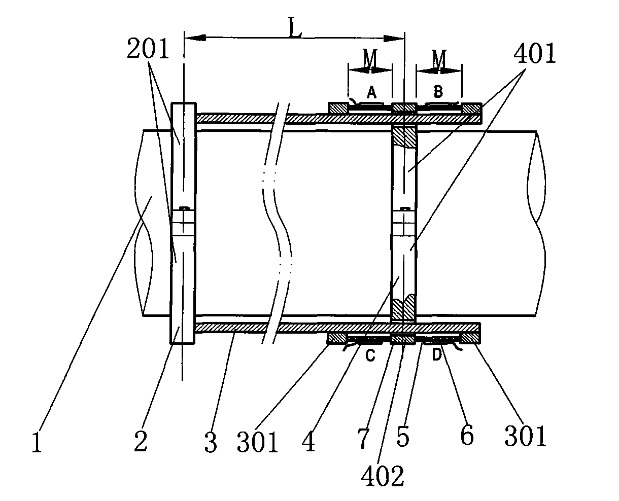
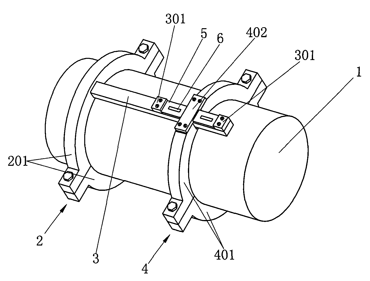
[0018] The specific implementation manners of the present invention will be further described in detail below in conjunction with the accompanying drawings.

[0019] Such as figure 1 , 2 As shown, the present invention includes a first positioning flange 2 and a second positioning flange 4, and the first positioning flange 2 and the second positioning flange 4 are fixedly installed on the shaft 1 at a certain distance. The two dowel bars 3 are arranged symmetrically, and are respectively slidingly sleeved in the chute 7 of the second positioning flange 4. One ends of the two dowel bars 3 are respectively welded on the first positioning flange 2. In this embodiment, The first positioning flange 2 is composed of two semi-circular flanges 201 connected, and the two semi-circular flanges 201 are fixedly connected by screws and sleeved on the shaft 1; the second positioning flange 4 is composed of two sliding grooves 7 The semi-circular flanges 401 are connected, and the two semi...


PUM


Abstract

The invention relates to an axle-system axial pulsating force measurement device, which is applicable for measurement of axial pulsating force and axial thrust and is characterized in that the device comprises a first positioning flange and a second positioning flange; the first positioning flange and the second positioning flange are fixedly arranged on an axle with certain spacing between; two dowel bars are symmetrically arranged and are respectively sheathed in a chute of the second positioning flange in a sliding way; four force reeds are arranged at two sides of the second positioning flange in a two-to-two symmetrical way; four strain gauges are arranged on the force reeds in an attaching way and adopt full-bridge connections among each other, and output ends thereof are connected with a telemetering data collection system. The invention provides the measurement device with simple structure and high measurement precision for pulsating force measurement, adopts microstrain measurement technology combining mechanical amplification and full-bridge connection of strain gauges, precisely measures the axial pulsating force of the axle system and provides precise parameters for the improved designing for reducing vibration noise of the axle system and related components.

Description

technical field [0001] The invention relates to a measuring device, in particular to an axial pulsating force measuring device for measuring a shaft system, which can be used for measuring the axial pulsating force and also for measuring the axial thrust. Background technique [0002] When ships and warships are sailing, the vibration and radiation noise of the stern are closely related to the complex structure of the stern, the main propulsion device and the wake field of the stern. Due to the inhomogeneity and unsteadiness of the propeller incoming flow, the hydrodynamic pulsation component acting on the propeller blades not only causes the propeller to directly radiate sound, but also excites the vibration of the bilge plate and blades above the propeller, which is transmitted through the shafting and bearing housing structure to the hull structure, causing stern vibration and radiating noise into the water. The measured data show that at low speed (4 knots), this part o...

Claims


Application Information

Patent Timeline
Patent Type & Authority Applications(China)
IPC IPC(8): G01L5/00G01L5/12
Inventor 吴文伟谢基榕
Owner 中国船舶重工集团公司第七〇二研究所
Why Eureka
Try Eureka