
Needle selecting cam control device for flat knitting machine

A control device and triangle technology, applied in knitting, weft knitting, textiles and papermaking, etc., can solve the problems that the needle selector cannot be reset, increase the noise, and weaken the driving force, etc., to achieve fast running speed, reliable and stable performance, and lighten the load effect

Inactive Publication Date: 2009-12-16
骆海生
View PDF0 Cites 12 Cited by
  • Summary
  • Abstract
  • Description
  • Claims
  • Application Information

AI Technical Summary

Problems solved by technology

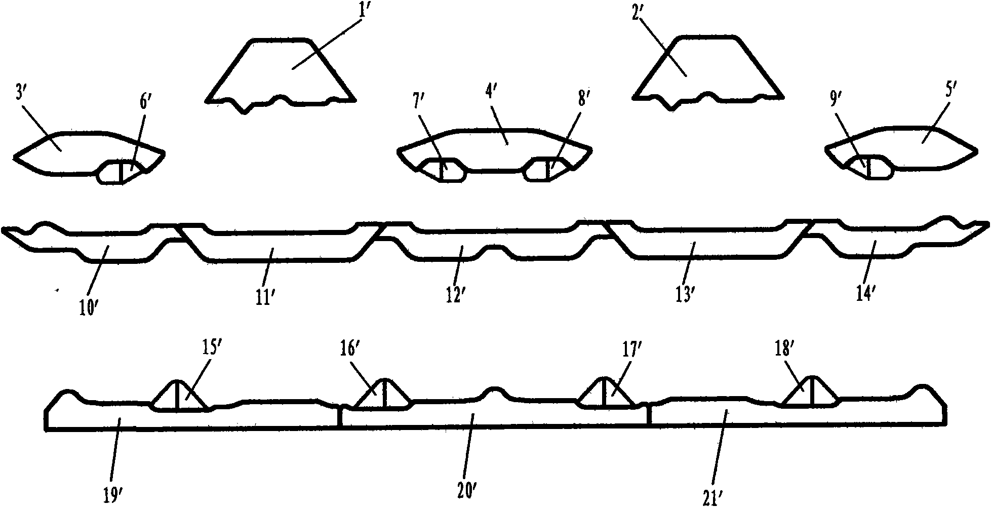
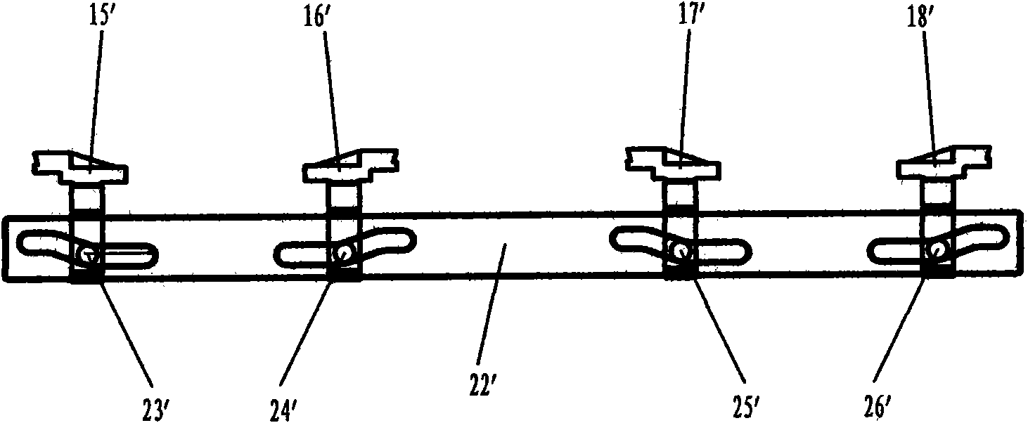
[0006] The disadvantages of the existing needle selection structure and needle selection method are as follows: 1. The structure is complex. Since the reset triangle and the needle lifting triangle are both movable, it is necessary to add a transmission mechanism and a drive mechanism, which makes the structure of the whole machine more compact. It is complex, and frequent activities often cause the triangle to be stuck, which will affect the accuracy of needle selection; 2. If the triangle needs to move, it must have a very complicated transmission device, and the driving source of this transmission device is a strong magnet , when the machine head is running, this strong magnet is tightly adsorbed on the guide rail of the machine head, thereby increasing the operating load of the machine head, increasing noise and increasing energy consumption. If the driving source is changed to a general magnet, the machine head The operating load will be reduced, but the driving force will be significantly weakened, and the drive will not be in place, causing the needle selection piece to fail or the needle selection piece cannot be reset, resulting in the machine not working normally

Method used


Image

  • Needle selecting cam control device for flat knitting machine
  • Needle selecting cam control device for flat knitting machine
  • Needle selecting cam control device for flat knitting machine

Examples


Embodiment Construction

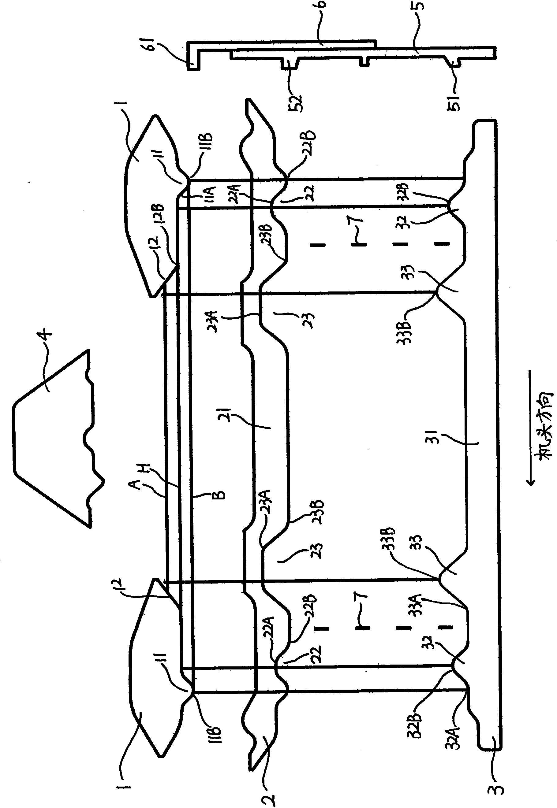
[0028] The needle selection cam control device of a flat knitting machine according to the present invention is arranged at the lower end of the flat knitting machine cam bottom plate relative to the knitting area, and controls a plurality of selector jacks 5 arranged together with knitting, and A plurality of needle presses 6 and each needle selection jack 5 have multiple bells, which can be moved up and down through the needle selection cam control device installed on the triangular bottom plate, so that the needle selection jacks can be adjusted according to the requirements of knitting with the cooperation of the needle selector. Needle selection.

[0029] The present invention includes at least one needle selection cam control unit (applied to one knitting cam in a single system), and may also include two or more needle selection cam control units (when the present invention is applied to two systems or multiple systems) , the following will take a unit as an example to i...


PUM


Abstract

The invention discloses a needle selecting cam control device for a flat knitting machine, which belongs to the technical field of textile machineries. The device comprises a stitch reset cam, a needle selection reset cam and a needle cast-on cam which are positioned below a knitting cam, are orderly, transversely and alternately arranged, and are fixedly arranged on a triangular bottom plate of the flat knitting machine, wherein the stitch preset cam and the needle selection reset cam form an upper rail and a lower rail with the needle cast-on cam respectively; the upper rail consisting of the stitch preset cam and the needle cast-on cam is used for finishing needle selection and needle cast-on; the lower rail consisting of the needle selection reset cam and the needle cast-on cam is used for finishing needle selection reset; the stitch reset cam, the needle selection reset cam and the needle cast-on cam are provided with a plurality of convex parts and concave parts respectively; the convex parts and the concave parts between the upper rail and the lower rail are embedded with each other; and a needle selecting piece performs needle raising or reset in the upper rail and the lower rail according to different flower pattern requirements through the interaction between the upper rail and the lower rail. The device has the advantages of simple structure, steady operation, and small part consumption.

Description

technical field [0001] The invention relates to a textile machine, in particular to a needle selection cam control device for controlling a needle selection piece of a flat knitting machine. Background technique [0002] In the prior art, the knitting of the flat knitting machine is controlled by cams, and a number of regular grooves are provided on the cam device of the flat knitting machine to control the needle selectors of the flat knitting machine. The stitches of the needle are pushed into the three knitting needle tracks of BAH according to the pattern, and the knitting needle is moved up and down regularly in the needle groove of the needle plate by moving the cam, and the knitting is completed through the action of the needle hook and the needle latch. [0003] In the needle selection cam control device of the existing flat knitting machine, the reset cam and the needle starting cam are all movable, and corresponding activities are carried out according to the runni...

Claims


Application Information

Patent Timeline
Patent Type & Authority Applications(China)
IPC IPC(8): D04B15/36
Inventor 骆海生
Owner 骆海生
Learn More